C-shaped double-magnet micro power generation device and wireless switch with power generation device
A technology for power generation devices and magnets, which is applied in the direction of electromechanical devices, electrical components, and static parts of magnetic circuits, etc., can solve the problems of increased manufacturing costs, weak current, and inconvenient manufacturing, and achieve low manufacturing costs, simple closed magnetic circuits, and reduced The effect of manufacturing costs
- Summary
- Abstract
- Description
- Claims
- Application Information
AI Technical Summary
Problems solved by technology
Method used
Image
Examples
Embodiment 1
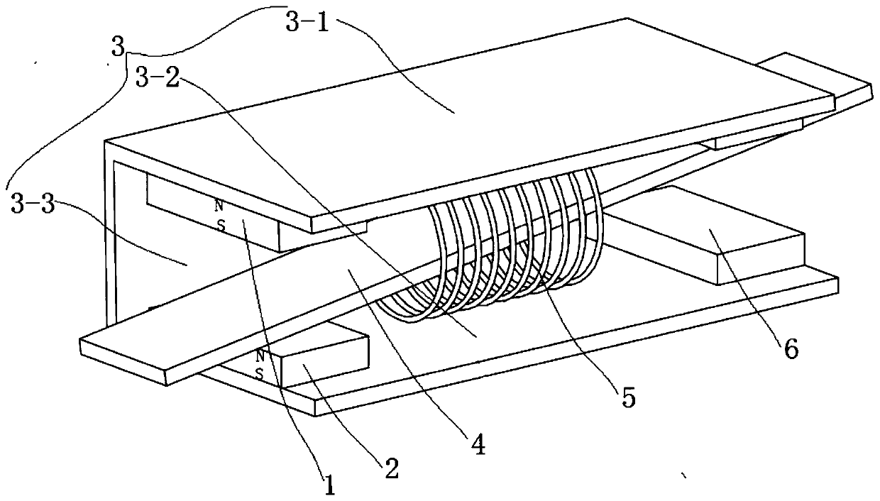
[0037] combine figure 1 , a C-type dual-magnet miniature power generation device in this embodiment includes a coil assembly and a permanent magnet assembly, and the permanent magnet assembly includes a first permanent magnet 1, a second permanent magnet 2 and a C-shaped soft magnetic frame 3. The C-shaped soft magnetic The frame 3 includes an upper soft magnetic plate 3-1, a lower soft magnetic plate 3-2 and a middle soft magnetic plate 3-3 connected to the upper soft magnetic plate 3-1 and the lower soft magnetic plate 3-2; the first permanent magnet 1 and The second permanent magnets 2 are all arranged in the C-shaped cavity of the C-shaped soft magnetic frame 3. The first permanent magnet 1 is fixed on the left end of the upper soft magnetic plate 3-1, and the second permanent magnet 2 is fixed on the lower soft magnetic plate 3-1. The left end of 2; the coil assembly includes a soft magnetic plate 4 and a coil 5, and the coil 5 is wound on the middle of the soft magnetic ...
Embodiment 2
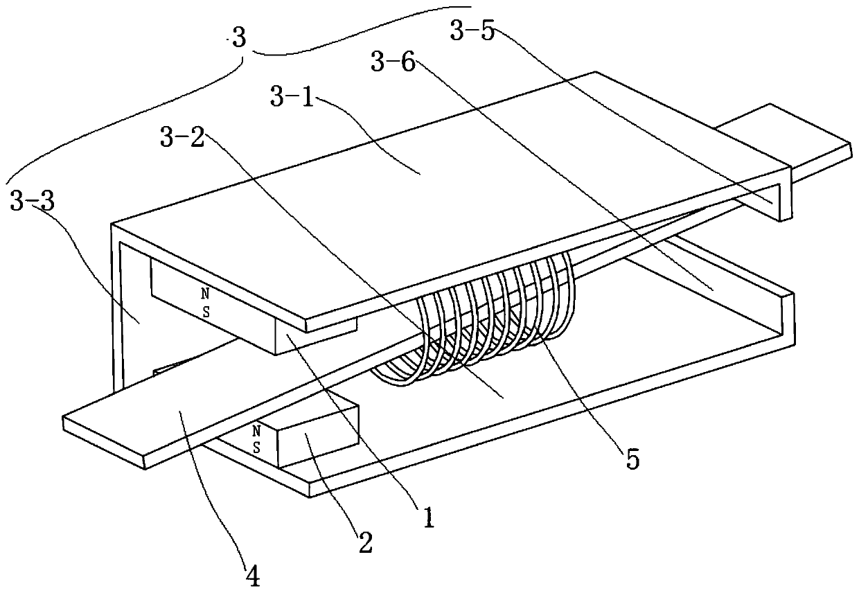
[0044] combine figure 2 , the basic structure of a C-type double-magnet micro-generating device of this embodiment is the same as that of Embodiment 1, the difference is that the upper vertical plate 3-5 is integrally formed on the right end of the upper soft magnetic plate 3-1, and the lower soft magnetic plate is integrally formed with the upper vertical plate 3-5. The right end of 3-2 is integrally formed with a lower vertical plate 3-6; the gap between the upper vertical plate 3-5 and the lower vertical plate 3-6 is equal to the gap between the first permanent magnet 1 and the second permanent magnet 2; installation One side of the two first installation cavities 7-5 on the left side of the seat I7 penetrates through the soft magnetic frame fixing section I7-2, so that the right end of the upper soft magnetic plate 3-1 and the lower soft magnetic plate 3-2 When the right end of the upper vertical plate 3-5 and the lower vertical plate 3-6 are inserted into the first upper...
Embodiment 3
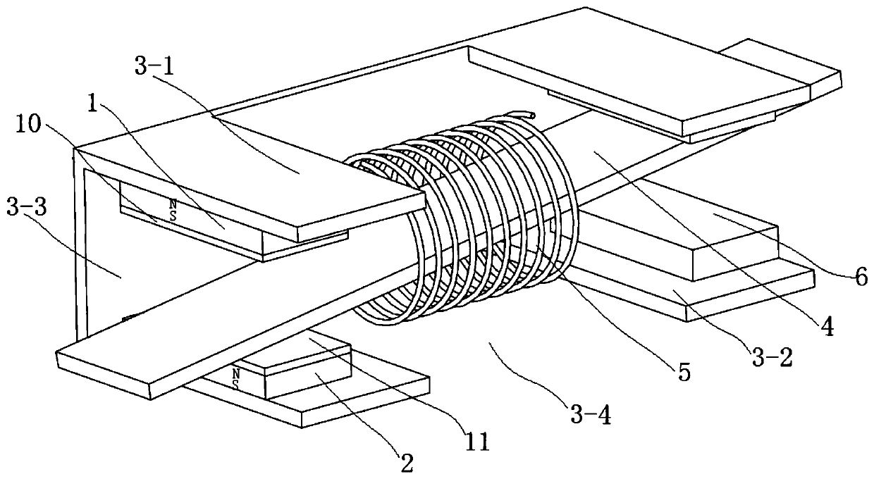
[0046] combine Figure 5 , a C-type dual-magnet micro-generating device in this embodiment includes a coil assembly and a permanent magnet assembly, and the permanent magnet assembly includes a first permanent magnet 1, a second permanent magnet 2 and two C-shaped soft magnetic frames 3 arranged opposite to each other , the two C-shaped soft magnetic frames 3 are arranged opposite each other up and down, and the two C-shaped soft magnetic frames 3 are connected together to form a rectangular cavity; the first permanent magnet 1 and the second permanent magnet 2 are both arranged in the rectangular cavity, and the A permanent magnet 1 is fixed at the left end of the upper surface of the rectangular cavity, and a second permanent magnet 2 is fixed at the left end of the lower surface of the rectangular cavity; the coil assembly includes a soft magnetic plate 4 and a coil 5, and the coil 5 is wound around the soft magnetic plate 4; the soft magnetic plate 4 is rotatably arranged ...
PUM
 Abstract
Description
Claims
Application Information
 - R&D
- Intellectual Property
- Life Sciences
- Materials
- Tech Scout
- Unparalleled Data Quality
- Higher Quality Content
- 60% Fewer Hallucinations
Browse by: Latest US Patents, China's latest patents, Technical Efficacy Thesaurus, Application Domain, Technology Topic, Popular Technical Reports.
© 2025 PatSnap. All rights reserved.Legal|Privacy policy|Modern Slavery Act Transparency Statement|Sitemap|About US| Contact US: help@patsnap.com


