Alignment structure

A technology for aligning parts and extending parts, which is applied in the direction of semiconductor/solid-state device parts, semiconductor devices, electrical components, etc., and can solve the problem of uneven coating of photoresist

Active Publication Date: 2022-07-12
PLAYNITRIDE DISPLAY CO LTD
View PDF12 Cites 0 Cited by
  • Summary
  • Abstract
  • Description
  • Claims
  • Application Information

AI Technical Summary

Problems solved by technology

[0003] The present invention is aimed at an alignment structure, using extensions to avoid the problem of uneven coating of photoresist

Method used


Image

  • Alignment structure
  • Alignment structure
  • Alignment structure

Examples


no. 1 example

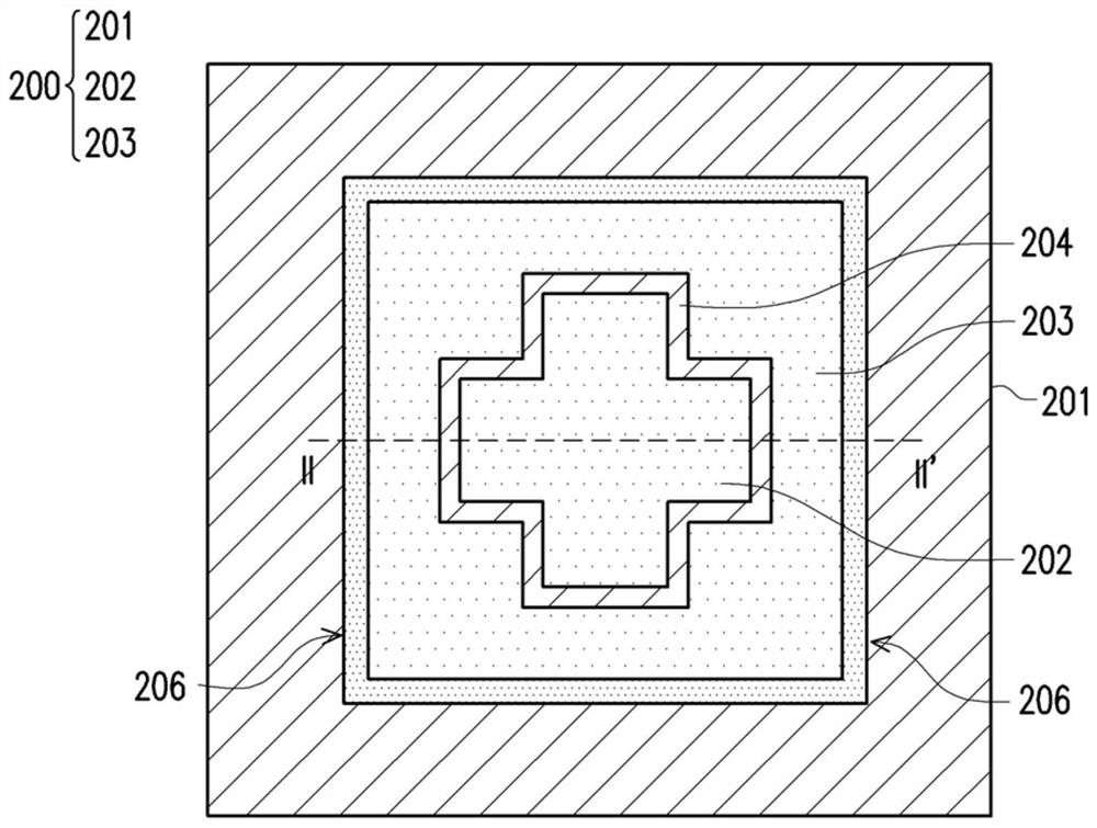
[0023] According to the first embodiment of the present invention, the alignment structure 200 includes a substrate 201 , an alignment portion 202 and an extension portion 203 . The alignment portion 202 is disposed on the substrate 201 , and the extension portion 203 is disposed on the substrate 201 . The extension portion 203 at least partially surrounds the alignment portion 202 and is spaced from the alignment portion 202 by a gap 204 . The side of the extension portion 203 close to the alignment portion 202 and the side of the alignment portion 202 close to the extension portion 203 are conformal to each other, that is, as Figure 1A As shown, the side of the alignment portion 202 close to the extension portion 203 is in the shape of a cross, and the side of the extension portion 203 close to the alignment portion 202 is also in the shape of a cross.

[0024] refer to Figure 1B , it can be seen that the photoresist 205 does not have a thin photoresist coating above the g...


PUM


Abstract

The present invention provides an alignment structure, which includes a substrate, an alignment portion, and an extension portion. The alignment portion is arranged on the substrate, the extension portion is arranged on the substrate, and the extension portion at least partially surrounds the alignment portion and is spaced from the alignment portion by a gap. The side of the extension part close to the alignment part and the side of the alignment part close to the extension part are conformal to each other.

Description

technical field [0001] The present invention relates to an alignment structure. Background technique [0002] Alignment structure (Alignment structure or Alignment key) plays an important role in the process, such as photolithography (photolithography) alignment, generally by direct metal plating or etching a pattern to make the alignment structure, but , After some processes, the metal or pattern will not be visible, or the photoresist coating around the alignment structure will be thinner due to the height difference between the alignment structure and its surrounding structures, resulting in uneven coating. The chromatic aberration makes the identification of the alignment structure inaccurate, thereby causing the problem of poor yield. SUMMARY OF THE INVENTION [0003] The present invention is directed to an alignment structure that utilizes an extension to avoid the problem of uneven coating of photoresist. [0004] According to an embodiment of the present inventio...

Claims


Application Information

Patent Timeline
Patent Type & Authority Patents(China)
IPC IPC(8): H01L23/544
CPCH01L23/544H01L2223/54426
Inventor 陈彦烨杨翔甯吴志凌彭钰雅
Owner PLAYNITRIDE DISPLAY CO LTD
Why Eureka
Try Eureka