


Quick Research
Generate reliable direction feasibility study reports for your R&D in just a few steps.

Technical Q&A
Discover and master advanced knowledge NOW. Basics, ideas, possibilities, all at once.

Find Solutions
As an expert in R&D theories, this can generate solutions to your technical problems instantly.

Evaluate Feasibility
Analyze your overall solution with one click, know your potential R&D risks in advance.

Monitor Landscape
Get weekly tech updates, stay abreast of the latest tech innovations and key insights.
Dual condenser of low-pressure drinking equipment
A drinking water equipment and condenser technology, which is applied in steam/steam condensers, water/sewage treatment equipment, beverage preparation equipment, etc., can solve the problems affecting the health of residents, drinking water sterilization, low efficiency, etc., to reduce Effects of hindering, improving efficiency, and lowering steam temperature
- Summary
- Abstract
- Description
- Claims
- Application Information
AI Technical Summary
Problems solved by technology
Method used
Image


Examples
Embodiment 1
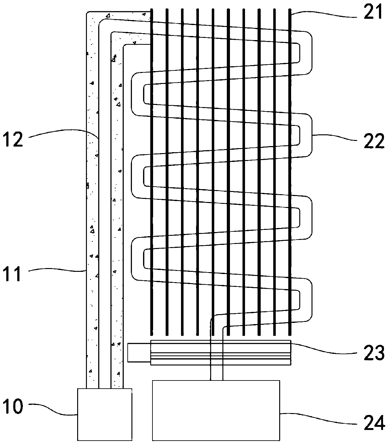
[0034] Such as figure 1 , figure 2 and image 3As shown, a double condenser of low-pressure drinking water equipment includes a steam generator, which is used in a low-pressure environment and can evaporate water in a low-pressure environment to form steam. The double condenser of the low-pressure drinking water equipment also includes Steam air-cooled unit 20 and steam liquid-cooled unit 30, wherein steam air-cooled unit 20 comprises air-cooled cooling fin group 21, boiling water tank 24, air-cooled condensation pipe 22 and air-cooled cross flow fan 23, and air-cooled condensation pipe 22 is arranged as "S" shape, the number of bends is not less than 8 times, and the whole forms a rectangular tortuous flow. In this way, in a limited space, the flow path of steam is increased, and the time of air cooling is increased at the same time, and the air cooling condenses One end of the pipe 22 is installed on the above-mentioned steam generator, and the other end communicates with...
Embodiment 2
[0036] Compared with Example 1, the following schemes are also included:
[0037] Such as image 3 As shown, the steam liquid cooling unit 30 also includes a liquid cooling fin set 31, a liquid cooling cross flow fan 33, a circulating water pump 37, a circulating water inlet pipe 38 and a circulating water outlet pipe 32, since a small amount of steam enters the steam liquid cooling unit 30. Therefore, the temperature of the condensate 35 will slowly rise. Due to the large specific heat capacity of the liquid itself, after absorbing heat, the speed of losing heat is also slow. Install a circulating water inlet pipe 38 and a circulating The water outlet pipe 32, the circulating water inlet pipe 38 and the circulating water outlet pipe 32 are connected to each other and form an "S"-shaped passage, and the liquid cooling fin group 31 is laid on the circulating water inlet pipe 38 and the circulating water outlet pipe 32 to facilitate liquid cooling and heat dissipation. The asse...
Embodiment 3
[0039] Compared with Example 2, the following schemes are also included:
[0040] Such as figure 2 As shown, the double condenser also includes a steam delivery pipe 12 and an insulation layer 11. Since the steam is delivered to the steam air-cooling unit 20 after the steam generator generates steam, there is still a distance in the middle, in order to avoid the steam from Condensation occurs within a certain distance and flows back into the steam generator. Therefore, one end of the steam delivery pipe 12 is installed at the outlet of the steam generator, and the other end of the steam delivery pipe 12 is installed at the inlet end of the air-cooled condensing pipe 22. At the same time, the steam delivery An insulation layer 11 is added to the outer surface of the pipe 12 to ensure that the temperature of the steam in the steam delivery pipe 12 will not decrease and condensation will not occur. This measure increases the efficiency of condensation from the side and reduces u...
PUM
 Abstract
Description
Claims
Application Information
 - R&D Engineer
- R&D Manager
- IP Professional
- Industry Leading Data Capabilities
- Powerful AI technology
- Patent DNA Extraction
Browse by: Latest US Patents, China's latest patents, Technical Efficacy Thesaurus, Application Domain, Technology Topic, Popular Technical Reports.
© 2024 PatSnap. All rights reserved.Legal|Privacy policy|Modern Slavery Act Transparency Statement|Sitemap|About US| Contact US: help@patsnap.com