Drying device for pottery fixed blank

A drying device and pottery technology, applied in drying, drying machine, heating device and other directions, can solve the problems of long time, unfavorable large-scale production, low production efficiency and the like

Inactive Publication Date: 2020-07-31
重庆市冠美廷陶瓷有限公司
View PDF0 Cites 2 Cited by
  • Summary
  • Abstract
  • Description
  • Claims
  • Application Information

AI Technical Summary

Problems solved by technology

[0002] The kiln firing is an important link in the ceramic preparation process. The ceramic body needs to be dried before the ceramic kiln is fired. Under normal circumstances, natural air drying takes a long time, which is not conducive to large-scale production, and the production efficiency is low. This requires When the embryo body drying device is used, the common ceramic embryo body drying device places the embryo body on the conveyor belt, and dries the embryo body when the conveyor belt passes through the drying device. This drying method is suitable for the embryo body (especially It is an embryo body with a big top and a small bottom) The inner cavity cannot play a good role in drying

Method used


Image

  • Drying device for pottery fixed blank
  • Drying device for pottery fixed blank
  • Drying device for pottery fixed blank

Examples


Embodiment

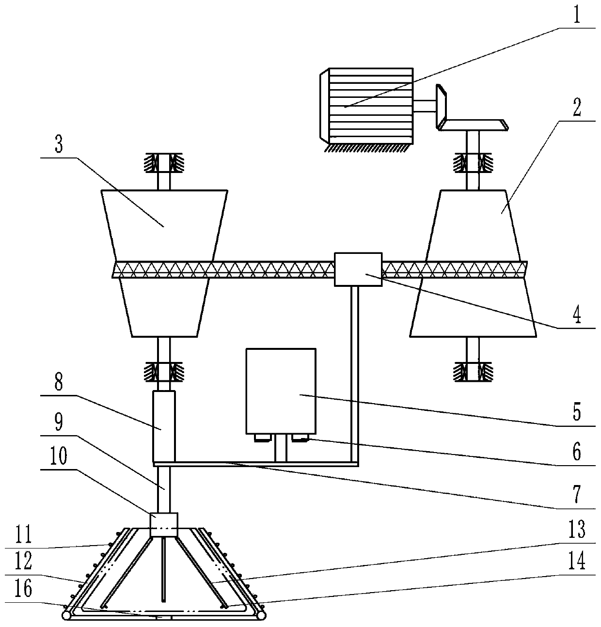
[0030] The utility model relates to a drying device for fixed embryos of pottery, which comprises a machine frame, a power part and a drying part under the power part.

[0031] like figure 1 As shown, the power part includes a motor, a driving shaft, a driven shaft, a hydraulic cylinder 5, a shift fork 7, a connecting rod and a rotating shaft 9, wherein the motor is fixed on the frame, and the driving shaft and the driven shaft are vertically arranged and The two ends are rotatably connected to the frame through bearings. The middle part of the driving shaft is provided with an active tapered roller 2, and the middle part of the driven shaft is provided with a driven tapered roller 3, wherein the active tapered roller 2 is small at the top and large at the bottom (that is, the active cone The diameter of the driven tapered roller 2 gradually increases from top to bottom), the driven tapered roller 3 is large at the top and small at the bottom (that is, the diameter of the driv...


PUM


Abstract

The invention discloses a drying device for pottery fixed blank. The drying device comprises a rack, a power part and a drying part positioned below the power part, wherein the power part comprises amotor, a drive shaft driven by the motor, a driven shaft, a hydraulic cylinder fixedly arranged on the rack, a shifting fork, a connecting rod and a rotary shaft, wherein the motor is fixedly arrangedon the rack; the drive shaft and the driven shaft are vertically arranged, and the two ends of each of the drive shaft and the driven shaft are rotatably connected onto the rack through bearings; themiddle part of the drive shaft is provided with a drive tapered roller; the middle part of the driven shaft is provided with a driven tapered roller; the drive tapered roller is small in top and is big in bottom; the driven tapered roller is big in top and is small in bottom; a drive belt is arranged between the drive tapered roller and the driven tapered roller; and the lower end of the driven shaft is in spline connection to the upper end of a rotary shaft. The drying device is higher in pottery manufacturing efficiency.

Description

technical field [0001] The invention relates to the technical field of pottery production and processing, in particular to a drying device for pottery preformation. Background technique [0002] The kiln firing is an important link in the ceramic preparation process. The ceramic body needs to be dried before the ceramic kiln is fired. Under normal circumstances, natural air drying takes a long time, which is not conducive to large-scale production, and the production efficiency is low. This requires When the embryo body drying device is used, the common ceramic embryo body drying device places the embryo body on the conveyor belt, and dries the embryo body when the conveyor belt passes through the drying device. This drying method is suitable for the embryo body (especially It is an embryo body with a big top and a small bottom) The inner cavity cannot play a good role in drying. Contents of the invention [0003] The object of the present invention is to provide a drying...

Claims


Application Information

Patent Timeline
IPC IPC(8): F26B3/347F26B11/08F26B23/04F26B25/00F26B25/02F26B25/04F26B25/12F26B25/16
CPCF26B3/347F26B11/08F26B23/04F26B25/003F26B25/02F26B25/04F26B25/12F26B25/16
Inventor 谢世华谢光扬
Owner 重庆市冠美廷陶瓷有限公司
Why Eureka
Try Eureka