A sunshade device for new energy vehicles

A technology for new energy vehicles and sunshade devices, which can be applied to vehicle parts, anti-glare equipment, transportation and packaging, etc. It can solve the problems of poor fixing effect, achieve the effect of convenient storage and storage, and reduce the occupied area

Active Publication Date: 2021-10-01
嵊州市万睿科技有限公司
View PDF11 Cites 0 Cited by
  • Summary
  • Abstract
  • Description
  • Claims
  • Application Information

AI Technical Summary

Problems solved by technology

[0003] The purpose of the present invention is to provide a sunshade device for new energy vehicles to solve the above-mentioned background technology. Although such devices in the prior art achieve the purpose of preventing exposure to the sun, most of them are fixed by buckles. not a good question

Method used


Image

  • A sunshade device for new energy vehicles
  • A sunshade device for new energy vehicles
  • A sunshade device for new energy vehicles

Examples


Embodiment 1

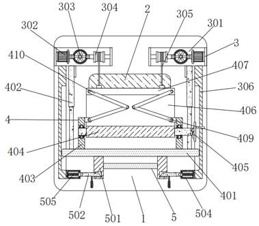
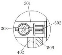
[0034] Embodiment 1: A sunshade device for new energy vehicles, comprising a first vertical plate 1 and a window 2, a window 2 is opened in the middle of the first vertical plate 1, the position of the window 2 corresponds to the position of the sunroof of the car, the first vertical plate Rotating device 3 is installed above the front end face of plate 1, and rotating device 3 comprises concave plate 301, motor 302, toothed disc 303, first roller 304, wire rope 305 and second riser 306, left and right concave plate 301 The rear end face is fixedly connected to the front end face of the first vertical plate 1, and the outer wall of the groove of the left and right concave plates 301 is fixedly connected with a motor 302. The model of the motor 302 is ECMA-E11320RS. The middle of the front end surface of the concave plate 301 is connected with a toothed plate 303 through the rotating shaft, and the toothed plate 303 can rotate at the concave plate 301 through the rotating shaft....

Embodiment 2

[0037] Embodiment 2: When the operator needs to use the sunshade device for new energy vehicles, the operator first connects the external power supply of the motor 302, starts the motor 302, and makes the motor 302 drive the gear plate 303 to rotate through the output shaft, and the gear plate 303 drives the second A roller wheel 304 rotates, and the first roller wheel 304 drives the second horizontal plate 407 to move through the wire rope 305, so that the second horizontal plate 407 drives the sunshade cloth 406 to move, and the sunshade cloth 406 drives the second roller wheel 404 to rotate, Simultaneously, the second horizontal plate 404 drives the first connecting rod 409 and the second connecting rod 410 to move, so that the purpose of sunshade is achieved, and the second handle 503 is pulled to make the second handle 503 drive the T-shaped inclined plate 502 to move, T The inclined plate 502 squeezes the spring 505, connects the external power supply of the electric push...


PUM


Abstract

The invention discloses a sunshade device for new energy vehicles, comprising a first vertical plate and a window, a window is opened in the middle of the first vertical plate, and a rotating device is installed above the front end of the first vertical plate. The sunshade device for new energy vehicles can make the sunshade cloth It can only be moved by this device, which prevents the sunshade from falling, and passes between the motor, gear plate, first roller, second roller, sunshade, wire rope, first connecting rod and second connecting rod, etc. The mutual cooperation can achieve the purpose of quickly opening the sunshade cloth, so that it is more convenient to use. Through the mutual cooperation between the second vertical board, the electric push rod, the second roller, the first handle and the sunshade cloth, this can be made. After the device is used, it is more convenient to fold and put away, thereby reducing the occupied area.

Description

technical field [0001] The invention relates to the technical field of new energy vehicles, in particular to a sunshade device for new energy vehicles. Background technique [0002] With the rapid development of China's economy, it has driven the use and development of new energy, among which the use of new energy vehicles is the most common. The promotion of new energy vehicles is also to meet the needs of environmental protection and oil crises, reduce or give up burning traditional gasoline or diesel The current mainstream models that drive the internal combustion engine, for the sake of beauty and practicality, many new energy vehicles have sunroofs on the roof, and the sunroof will make the interior of the car rise stably in hot summer, so it is necessary to install sunshade devices, although the current There are such devices in the art to prevent exposure to the sun, but most of them are fixed by buckles, the fixing effect is not good, and it is also very troublesome ...

Claims


Application Information

Patent Timeline
Patent Type & Authority Patents(China)
IPC IPC(8): B60J3/02
CPCB60J3/02
Inventor 周兰兰张利英周肇炎
Owner 嵊州市万睿科技有限公司
Why Eureka
Try Eureka