Numerically controlled vertical lathe

A numerical control vertical and lathe technology, which is applied in the field of numerical control lathes, can solve the problems of increased processing cost, complicated cleaning and disassembly, and high maintenance cost, and achieves the effects of reducing processing cost, facilitating separation from suction cups, and high clamping firmness.

Inactive Publication Date: 2020-07-31
钟金梅
View PDF5 Cites 2 Cited by
  • Summary
  • Abstract
  • Description
  • Claims
  • Application Information

AI Technical Summary

Problems solved by technology

[0003] The chucks used in the existing CNC vertical lathes use the rotation of the screw to drive the translation of the nut pair to adjust the displacement of the clamping block, so as to clamp the workpiece. Long-term use requires the screw and the nut pair to be adjusted. Cleaning is required for the precise and unimpeded translation of the nut pair, and the screw rod and the nut pair are both built in the chuck, so cleaning and disassembly are extremely cumbersome;
[0004] In addition, according to the number of jaws, chucks can be divided into two-jaw chucks, three-jaw chucks, four-jaw chucks, and six-jaw chucks. For different shapes of workpieces to be processed, chucks with different numbers of jaws need to be purchased. Chucks with various numbers of jaws will increase the processing cost invisibly, and need to replace the chucks, the operation is quite cumbersome and the maintenance cost is high

Method used


Image

  • Numerically controlled vertical lathe
  • Numerically controlled vertical lathe
  • Numerically controlled vertical lathe

Examples


Embodiment 1

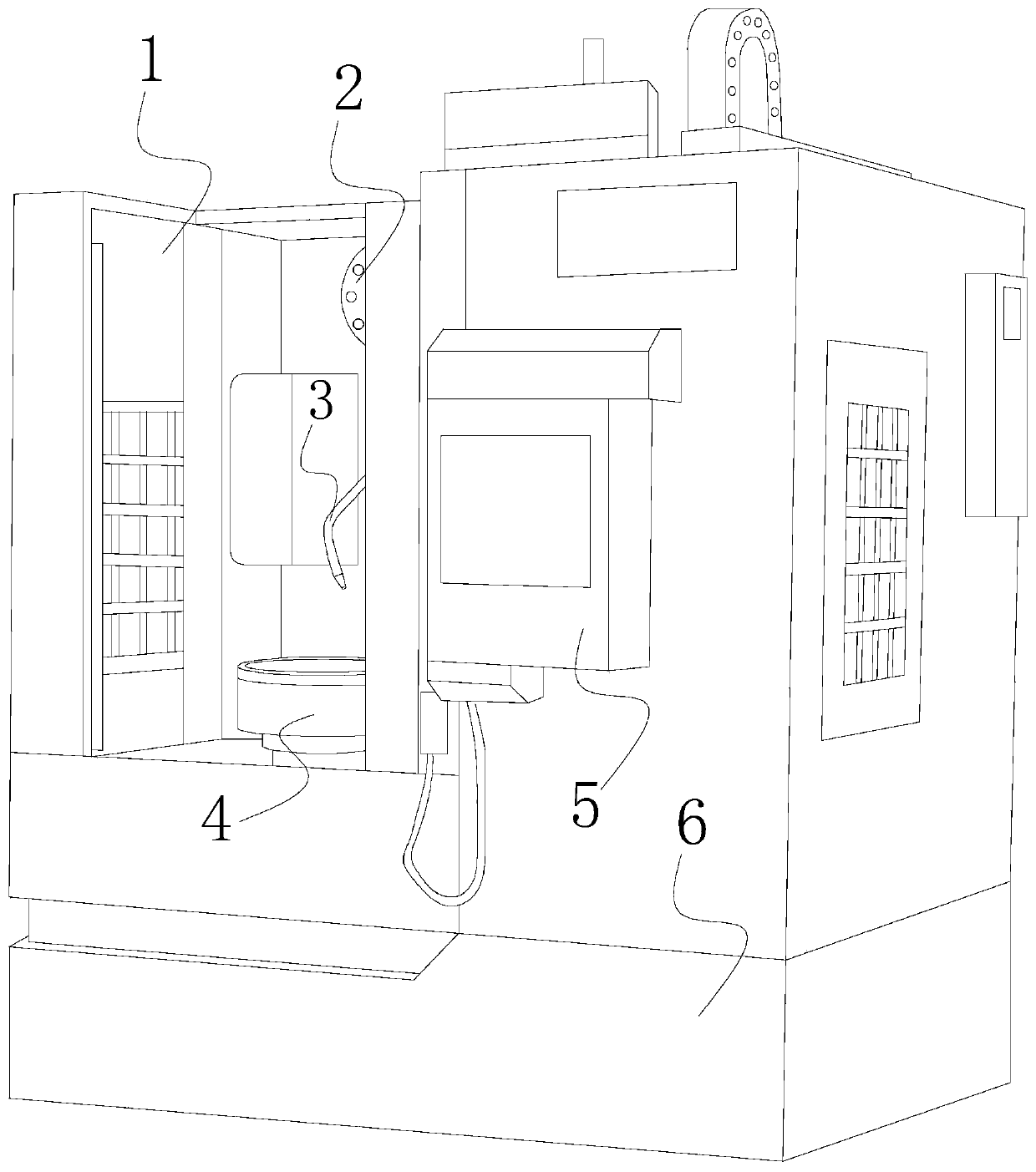
[0038] see figure 1 , the present invention provides a technical scheme of a numerically controlled vertical lathe: its structure includes a vertical bed body 1, a cutter head device 2, a cooling liquid cooling device 3, a chuck 4 for workpieces to be processed, a controller 5, and a base 6. The bottom of the vertical bed body 1 is fixed with a base 6, the outside of the vertical bed body 1 is equipped with a controller 5, and the vertical bed body 1 is provided with a cutter head device 2, a coolant cooling device 3, and a workpiece to be processed. Chuck 4;

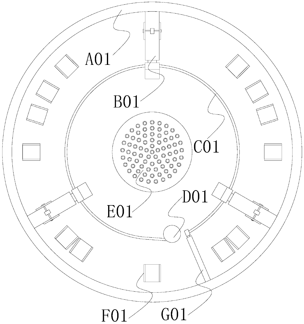
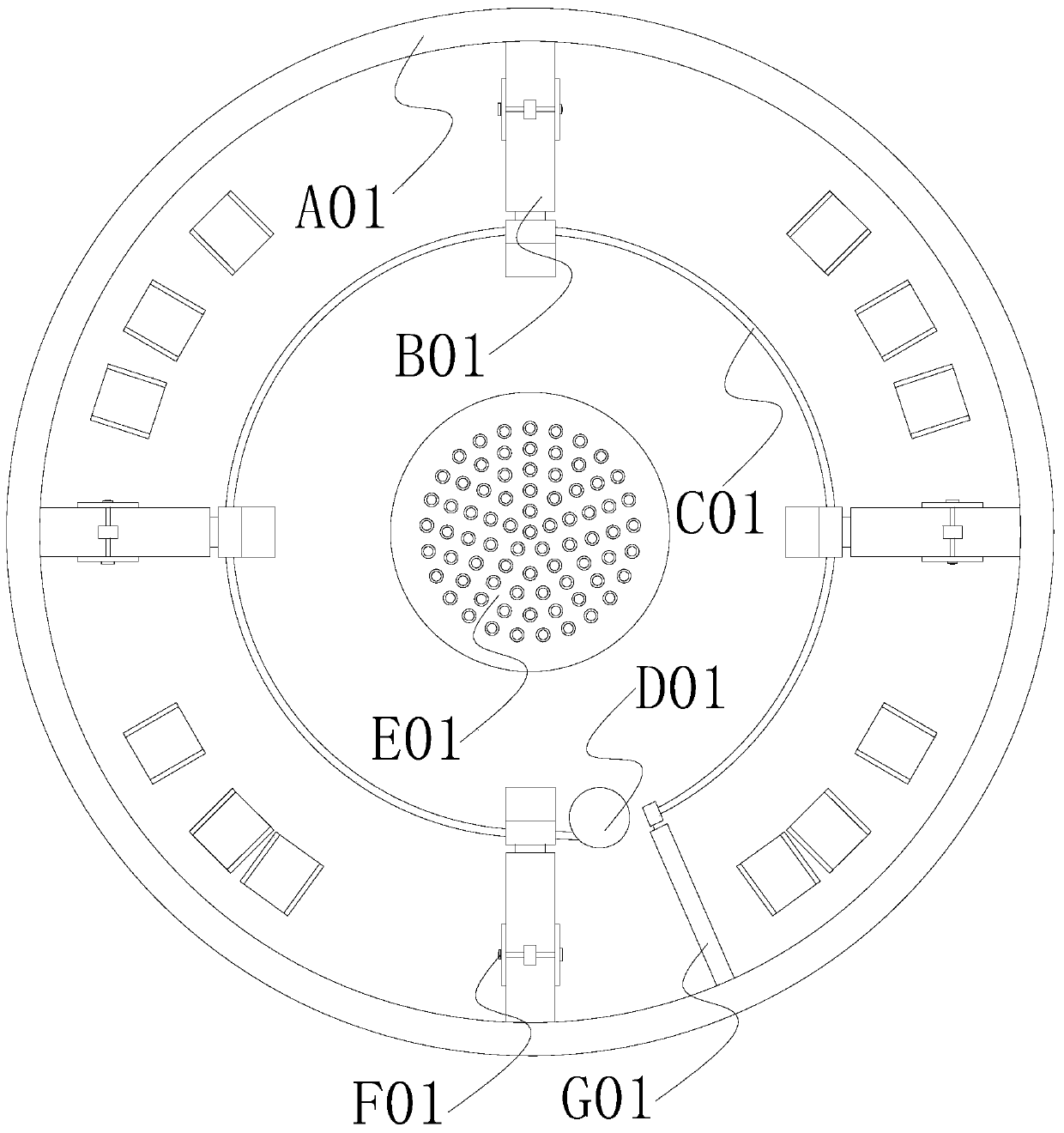
[0039] see Figure 2-7 The chuck 4 of the workpiece to be processed includes a chassis A01, a clamping group B01, a spring C01, a spring reel D01, a suction cup mechanism E01, a mounting seat F01, and a telescopic rod G01. The central position of the chassis A01 is provided with The suction cup mechanism E01, the chassis A01 is mechanically connected to the clamping group B01 through the mounting seat F01, the clampi...

Embodiment 2

[0043] see figure 1 , the present invention provides a technical scheme of a numerically controlled vertical lathe: its structure includes a vertical bed body 1, a cutter head device 2, a cooling liquid cooling device 3, a chuck 4 for workpieces to be processed, a controller 5, and a base 6. The bottom of the vertical bed body 1 is fixed with a base 6, the outside of the vertical bed body 1 is equipped with a controller 5, and the vertical bed body 1 is provided with a cutter head device 2, a coolant cooling device 3, and a workpiece to be processed. Chuck 4;

[0044] see Figure 2-7 The chuck 4 of the workpiece to be processed includes a chassis A01, a clamping group B01, a spring C01, a spring reel D01, a suction cup mechanism E01, a mounting seat F01, and a telescopic rod G01. The central position of the chassis A01 is provided with The suction cup mechanism E01, the chassis A01 is mechanically connected to the clamping group B01 through the mounting seat F01, the clampi...


PUM


Abstract

The invention discloses a numerically controlled vertical lathe. The numerically controlled vertical lathe structurally comprises a vertical lathe body, a cutter disc device, a coolant cooling device,a to-be-machined workpiece chuck, a controller and a pedestal, wherein the pedestal is fixed to the bottom of the vertical lathe body, and the controller is installed outside the vertical lathe body.A spring is adopted to adjust the displacement of anti-slip clamping blocks, and cleaning can be easily and conveniently performed without detaching the spring; through the cooperation of clamping sets and mounting bases, a worker can selectively increase or decrease the number of the clamping sets according to the shapes of to-be-machined workpieces, operation is easy, the numerically controlledvertical lathe can adapt to the to-be-machined workpieces in different shapes, then the to-be-machined workpieces can be clamped, the application range is wide, and the machining cost is reduced; andthrough the cooperation of the clamping sets and the spring, the spring can adjust the multiple clamping sets at the same time, the adjustment speed is high, the efficiency is high, meanwhile, the clamping sets can clamp to-be-machined workpieces of different specifications and dimensions, the clamping firmness is high, and the machining quality can be easily improved.

Description

technical field [0001] The invention relates to the technical field of numerically controlled lathes, in particular to a numerically controlled vertical lathe. Background technique [0002] CNC vertical lathe, with good stability and anti-seismic performance, vertical structure, convenient clamping of workpieces, small footprint, suitable for processing high-strength cast iron bases and columns of medium and small discs and cover parts. [0003] The chucks used in the existing CNC vertical lathes use the rotation of the screw to drive the translation of the nut pair to adjust the displacement of the clamping block, so as to clamp the workpiece. Long-term use needs to adjust the screw and the nut pair. Cleaning is required for the precise and unimpeded translation of the nut pair, and the screw rod and the nut pair are both built in the chuck, so cleaning and disassembly are extremely cumbersome; [0004] In addition, according to the number of jaws, chucks can be divided in...

Claims


Application Information

Patent Timeline
IPC IPC(8): B23B31/02B23B31/16
CPCB23B31/02B23B31/16
Inventor 钟金梅
Owner 钟金梅
Why Eureka
Try Eureka