
Novel acoustic motor and implementation method thereof

A technology of sound waves and motors, which is applied in the field of new sound wave motors and its realization, can solve problems such as failure to meet customer requirements, small torque, etc., achieve good vibration effect and strengthen the effect of driving magnetic field

Pending Publication Date: 2020-07-28
ZHEJIANG DONGYANG CHENGJI ELECTRO MECHANICS CO LTD
View PDF0 Cites 2 Cited by
  • Summary
  • Abstract
  • Description
  • Claims
  • Application Information

AI Technical Summary

Problems solved by technology

[0003] With the development of consumer electronics, the requirements for the vibration effect of the acoustic wave motor are getting higher and higher. The existing technology of the acoustic wave motor only has a pair of plates, and the torque generated by the work is small, which is increasingly unable to meet the requirements of customers.

Method used


Image

  • Novel acoustic motor and implementation method thereof
  • Novel acoustic motor and implementation method thereof
  • Novel acoustic motor and implementation method thereof

Examples


Embodiment 1

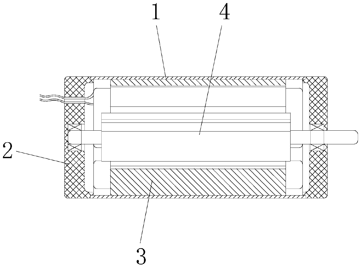
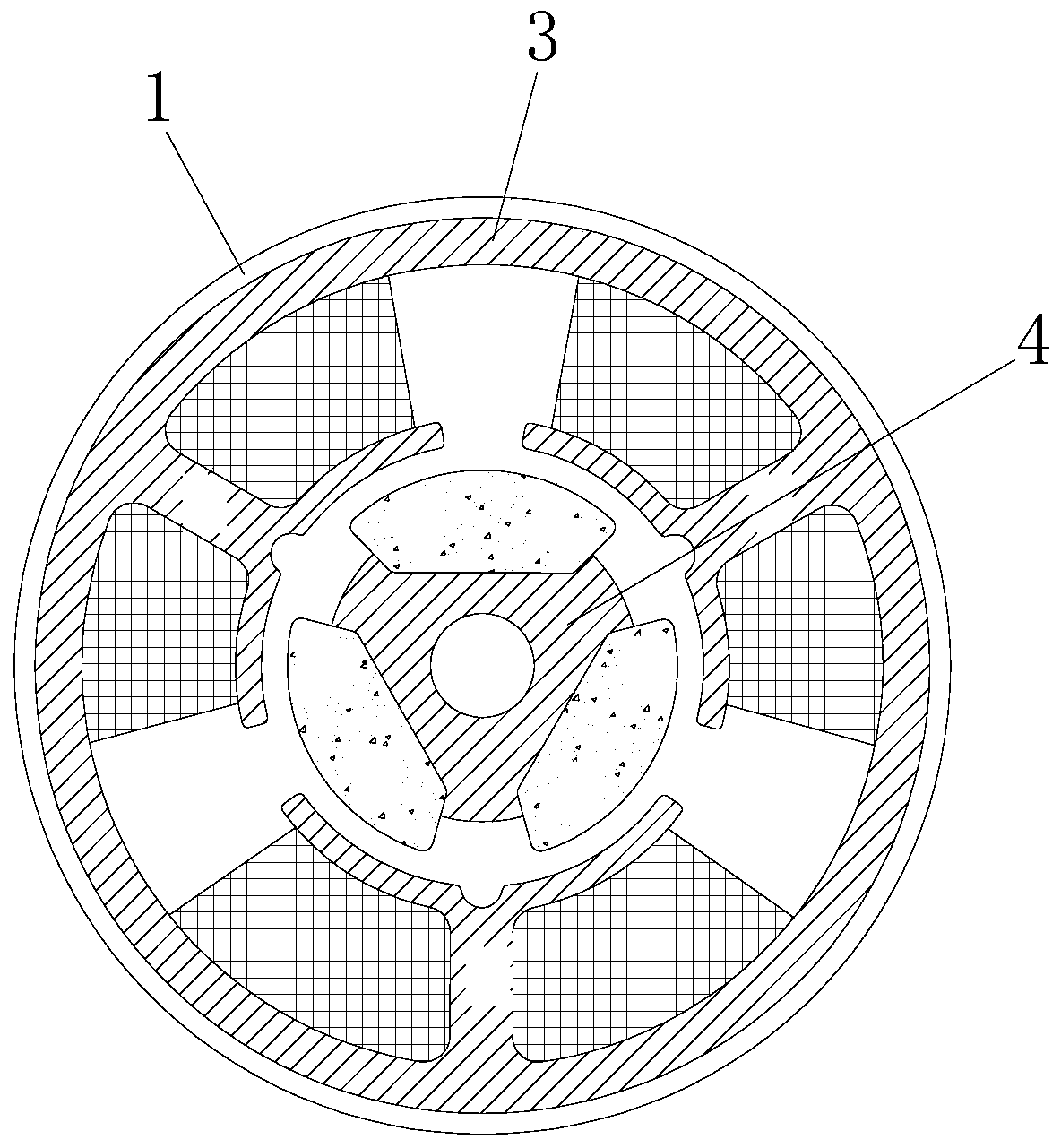
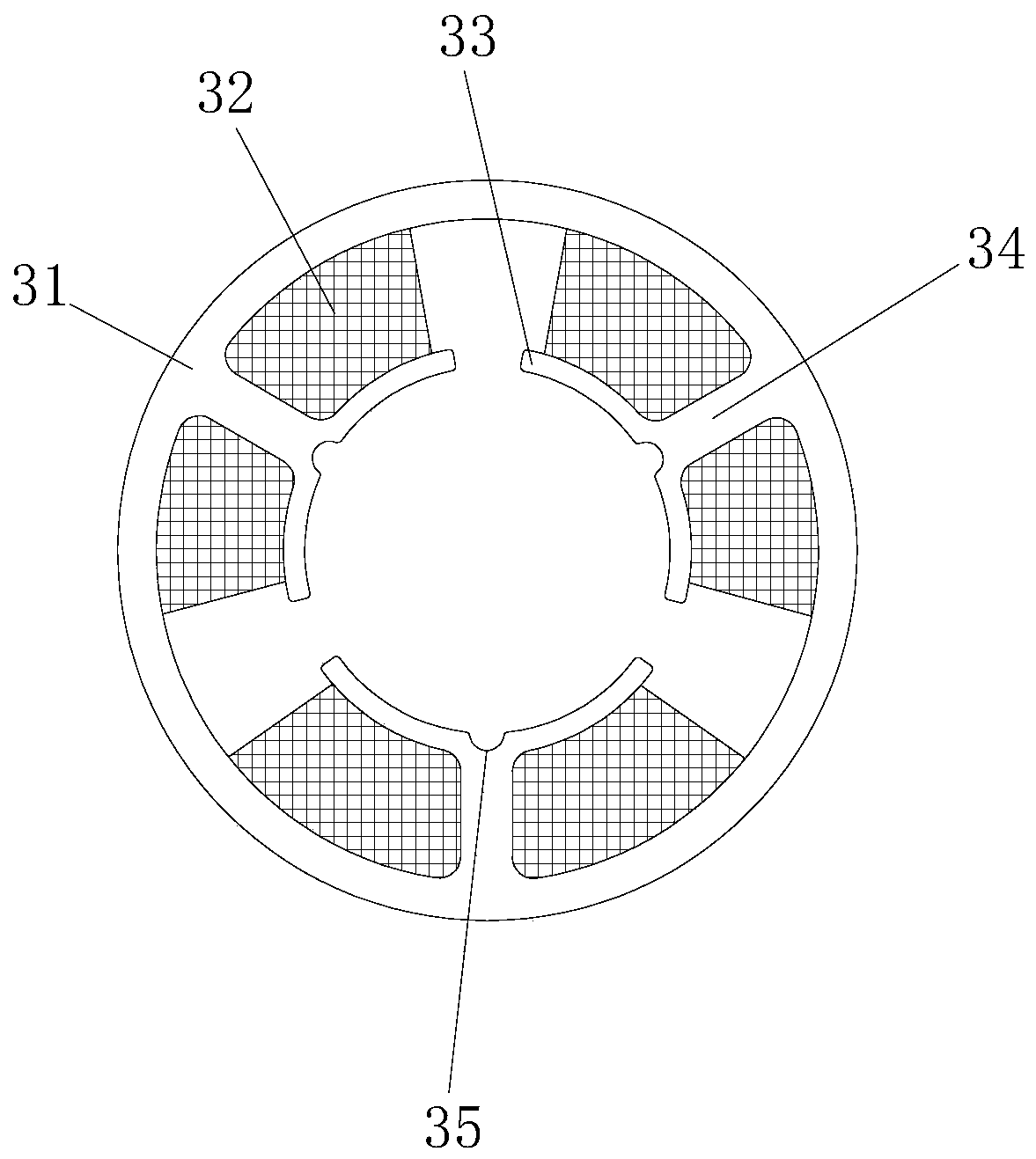
[0033] see Figure 1-7 , the present invention provides the following technical solutions: a new type of acoustic wave motor, including a casing 1, a stator assembly 3 is provided on the inner wall of the casing 1, a rotor assembly 4 is provided inside the stator assembly 3, and one side of the casing 1 is connected with The end cover 2, the rotor assembly 4 are rotationally connected with the end cover 2 and the casing 1, the stator assembly 3 includes a stator core 31, a coil 32 and a winding core 34, wherein the stator core 31 is connected to the inner wall of the casing 1, and the stator The iron core 31 is a hollow cylindrical structure. Three winding cores 34 are arranged at equal intervals on the inner wall of the stator iron core 31 . Coils 32 are wound on the winding cores 34 . The three coils 32 are connected in parallel.

[0034] Further, a pole plate 33 is connected to the side of the winding core 34 away from the stator core 31 , and the pole plate 33 has an arc-s...

Embodiment 2

[0043] The difference between this embodiment and Embodiment 1 lies in: further, a notch 35 is provided at the middle position of the pole plate 33 .

[0044] By adopting the above-mentioned technical scheme, under normal circumstances, when the coil 32 is energized, the pole plate 33 will generate a corresponding magnetic field, and it will be evenly distributed on the surface of the pole plate 33; The notch 35 forms two magnetic fields as boundaries.

[0045] Further, the implementation method of the novel acoustic wave motor described in the present invention includes the following steps:

[0046] (1), the stator assembly 3: the stator core 31, the pole plate 33 and the winding core 34 are stamped and formed by a magnetically conductive material, and the coils 32 are wound in the same direction on the three winding cores 34, and the three coils 32 are connected in parallel;

[0047] (2) Rotor assembly 4: the rotor core 41 is connected to the rotating shaft 43 through an in...


PUM


Abstract

The invention discloses a novel sound wave motor, which comprises a casing, wherein a stator assembly is arranged on the inner wall of the casing, a rotor assembly is arranged in the stator assembly,one side of the casing is connected with an end cover, the rotor assembly is rotatably connected with the end cover and the casing, the stator assembly comprises a stator iron core, coils and windingcores, the stator iron core is connected to the inner wall of the casing, the stator iron core is of a hollow cylinder structure, the three winding cores are arranged on the inner wall of the stator iron core at equal intervals, the coils are wound on the winding cores, and the three coils are connected in parallel. The invention further discloses an implementation method of the novel sound wave motor. According to the invention, the internal space of the casing is fully utilized, and the three coils are arranged in the casing and are connected in parallel, so that a strong electric field canbe generated when the coils are electrified so as to increase the torque; and the three magnetic steels are arranged on the rotor iron core, so that the driving magnetic field is enhanced so as to maximize the torque.

Description

technical field [0001] The invention belongs to the technical field of sound wave motors, and in particular relates to a novel sound wave motor and its realization method. Background technique [0002] Acoustic motor refers to an electromagnetic device that converts or transmits electric energy according to the law of electromagnetic induction. Its main function is to generate driving torque, which can be used as a power source for electrical appliances or various machines, such as the motor core of an electric toothbrush. After the sound wave motor is powered on, under the control of the control circuit, the sound wave motor circulates to generate a high-frequency vibration, which in turn drives the toothbrush head to generate high-frequency vibration. [0003] With the development of consumer electronics, the requirements for the vibration effect of the sound wave motor are getting higher and higher. The sound wave motor in the prior art only has a pair of plates, and the ...

Claims


Application Information

Patent Timeline
Patent Type & Authority Applications(China)
IPC IPC(8): H02K33/14
CPCH02K33/14
Inventor 何振高
Owner ZHEJIANG DONGYANG CHENGJI ELECTRO MECHANICS CO LTD
Learn More