Sensor life test system and working method

A life test and sensor technology, applied to instruments, measuring devices, measuring fluid pressure, etc., can solve problems such as long cycle time and poor verification accuracy, and achieve the effect of ensuring detection accuracy and improving the test range

Inactive Publication Date: 2020-07-24
CHINA RAILWAY ENGINEERING EQUIPMENT GROUP CO LTD
View PDF18 Cites 1 Cited by
  • Summary
  • Abstract
  • Description
  • Claims
  • Application Information

AI Technical Summary

Problems solved by technology

[0004] Aiming at the technical problems that the current sensor can verify the life of the sensor through long-term observation in the later period, the accuracy of the whole verification is poor, and the cycle is long, the present invention proposes a sensor life test system

Method used


Image

  • Sensor life test system and working method
  • Sensor life test system and working method

Examples


Embodiment 1

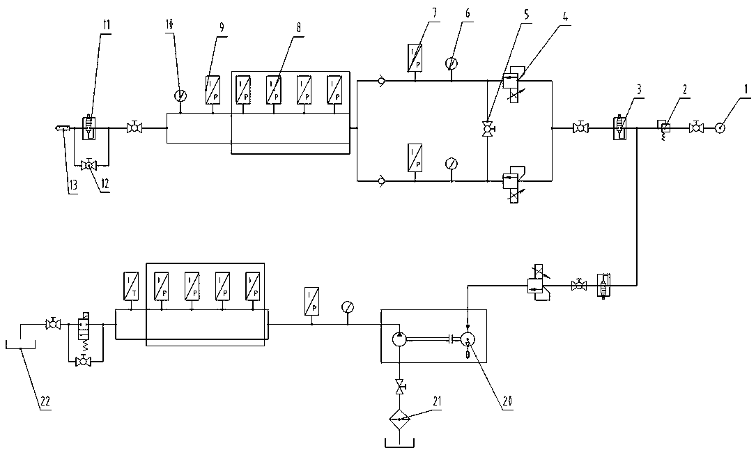
[0030] Embodiment 1: as figure 1 As shown, a sensor life test system includes an air source 1, and the air source 1 is connected to the air processing pipe network, and the air processing pipe network is respectively connected to the low-pressure test pipe network and the high-pressure test pipe network, which can test the sensor in the The test is carried out under different pressure conditions of low pressure or high pressure, which greatly improves the test range; the first pressure control pipeline and the second pressure control pipeline are respectively arranged in the low pressure test pipe network and the high pressure test pipe network, and the low pressure test pipe network and the The high-pressure test pipe network is equipped with sensor test pipelines and pressure relief pipelines, and the end of the low-pressure test pipe network is provided with a silencer. The silencer 13 can ensure that the noise of the test bench is at the lowest level when the pressure relie...

Embodiment 2

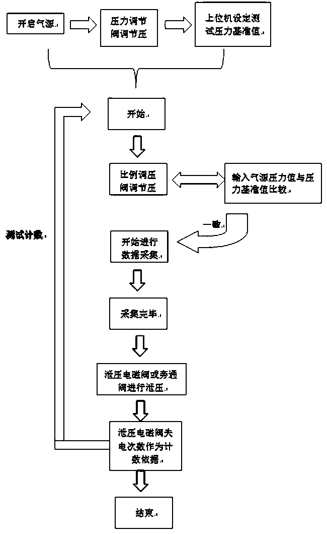
[0038] Example 2: as figure 2 As shown, a working method of a sensor life test system comprises the following steps:

[0039] S1. First turn on the air source 1, and the host computer controls the pressure regulating valve in the air processing pipeline to adjust the pressure of the input air source so that the output pressure of the air source is within a safe range, and then set the test pressure standard value through the host computer;

[0040] S2. The input air source enters the pressure control pipeline, and the upper computer controls the proportional pressure regulating valve in the pressure control pipeline to adjust the pressure of the input air source according to the set test pressure standard value, and the pressure detection in the pressure control pipeline The sensor detects the input air source pressure value in real time, and the upper computer receives the input air source pressure value detected by the pressure detection sensor in real time, and the upper c...


PUM


Abstract

The invention provides a sensor life test system and a working method. The sensor life test system comprises an air source, wherein the air source communicates with an air processing pipe network, andthe air processing pipe network respectively communicates with a low-pressure test pipe network and a high-pressure test pipe network; a first pressure control pipeline and a second pressure controlpipeline are respectively arranged in the low-pressure test pipe network and the high-pressure test pipe network; a sensor test pipeline and a pressure relief pipeline are arranged in each of the low-pressure test pipe network and the high-pressure test pipe network, the first pressure control pipeline and the second pressure control pipeline both communicate with the sensor test pipeline, and thesensor test pipeline communicates with the pressure relief pipeline; and the air processing pipe network, the first pressure control pipeline, the second pressure control pipeline, the sensor test pipeline and the pressure relief pipeline are all connected with an upper computer. According to the invention, through real-time data acquisition of automatic pressurization and pressure relief processes, the sensor life test is effectively carried out, the overall operation is simple, and remote control can be realized.

Description

technical field [0001] The invention relates to the technical field of sensor testing, in particular to a sensor life test system and working method. Background technique [0002] As a special equipment for sensor testing, the sensor test bench is widely used in the process of sensor production and testing. In the current sensor detection equipment, the life of the sensor is generally unable to be verified. The existing method is generally configured and used, and the reliability of the sensor is analyzed during the use process, and the purpose of verifying the life of the sensor is achieved through long-term observation in the later period. [0003] Generally speaking, due to the different operating conditions of the sensors, some sensors cannot be well identified in the use of whether the output signal is normal. At present, the test bench for the life test of the formed sensor is almost blank. Conditional testing users will make testing devices according to their own nee...

Claims


Application Information

Patent Timeline
Patent Type & Authority Applications(China)
IPC IPC(8): G01L27/00
CPCG01L27/00
Inventor 张杰周小磊赵云辉俞培德郭付军李光顾永升张龙飞高可可袁丹刘晓瑞
Owner CHINA RAILWAY ENGINEERING EQUIPMENT GROUP CO LTD
Why Eureka
Try Eureka