
Finned tube and heat exchanger

A finned tube and heat exchanger technology, applied in the field of heat exchangers, can solve the problems of low thermal conductivity, reduced heat exchange effect, and the inability of heat exchangers to operate efficiently and safely.

Pending Publication Date: 2020-07-24
DATANG ENVIRONMENT IND GRP +1
View PDF0 Cites 2 Cited by
  • Summary
  • Abstract
  • Description
  • Claims
  • Application Information

AI Technical Summary

Problems solved by technology

[0003] In actual production practice, the flue gas entering the heat exchanger often carries a large amount of fly ash. When the flue gas flows in the H-shaped finned tube bundle, there will be obvious air separation and backflow area on the leeward side of the finned tube. The flue gas flow rate inside the zone is low, the heat transfer effect will be reduced, and dust accumulation is easy to occur
Due to the low thermal conductivity of dust accumulation, the heat transfer performance of finned tubes will further deteriorate with the increase of dust accumulation, and the heat exchanger cannot operate efficiently and safely.

Method used


Image

  • Finned tube and heat exchanger
  • Finned tube and heat exchanger
  • Finned tube and heat exchanger

Examples


Embodiment Construction

[0034] The technical solutions of the present invention will be clearly and completely described below in conjunction with the embodiments. Obviously, the described embodiments are part of the embodiments of the present invention, but not all of them. Based on the embodiments of the present invention, all other embodiments obtained by persons of ordinary skill in the art without making creative efforts belong to the protection scope of the present invention.

[0035] In describing the present invention, it is to be understood that the terms "center", "longitudinal", "transverse", "length", "width", "thickness", "upper", "lower", "front", " Back", "Left", "Right", "Straight", "Horizontal", "Top", "Bottom", "Inner", "Outer", "Clockwise", "Counterclockwise", etc. or The positional relationship is based on the orientation or positional relationship shown in the drawings, which is only for the convenience of describing the present invention and simplifying the description, rather t...


PUM


Abstract

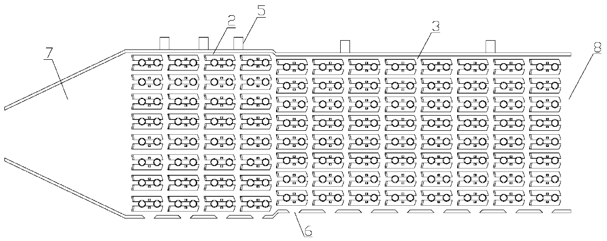
The present invention provides a finned tube and a heat exchanger. The finned tube comprises a base tube and a plurality of fin groups arranged in the axial direction of the base tube and connected with the outer wall of the base tube, and the fin groups are arranged in parallel; each fin group comprises two fins arranged in a mirror image, each fin is divided into three parts in the length direction of the corresponding fin, the first part is the windward area, the second part is the reflux area, and the third part is the leeward area; and a vortex generator is arranged on each windward area,a reflux blocking device is arranged on each reflux area, and the end of each leeward area is of a fillet structure. According to the finned tube, each windward area has better heat transfer condition and has better heat transfer capacity by additionally arranging the corresponding vortex generator; each reflux area is provided with the corresponding reflux blocking device, the reflux can be reduced or even eliminated, and the ash deposition is reduced; and the heat transfer effect of each leeward area is poor, the ash deposition is more, and the fillet structure is adopted on the reflux so as to reduce the flow resistance effectively.

Description

technical field [0001] The invention relates to the technical field of heat exchangers, in particular to a finned tube and a heat exchanger. Background technique [0002] Energy is an important basis for human economic and social progress. With the continuous growth of energy consumption in my country, energy conservation and emission reduction has become a long-term policy for my country's economic and social development. Thermal power plants account for the largest proportion in the power industry, and it is very urgent to improve the energy utilization efficiency of thermal power units. Coal-fired power plants are usually equipped with economizers to recover the waste heat of flue gas to achieve the purpose of energy saving. It is a common way to increase the heat exchange area of ​​the heat exchange tube by adding fins to enhance the heat exchange. H-type finned tubes have high finning coefficient, good heat transfer performance, and strong anti-dusting ability, and ar...

Claims


Application Information

Patent Timeline
IPC IPC(8): F28F1/32F28D7/16F23J15/02F23J15/06
CPCF23J15/022F23J15/06F28D7/16F28F1/32Y02E20/30
Inventor 张国柱张钧泰谷小兵李本锋刘忠秋
Owner DATANG ENVIRONMENT IND GRP
Learn More