
Water-saving blast furnace cooling wall structure with multiple layers of water supply pipes and application process thereof

A technology of cooling wall and water supply pipe, applied in the direction of cooling device, etc., can solve the problems affecting the safe production and longevity of blast furnace, the furnace shell is heated and deformed, the output is reduced and the consumption is increased, so as to achieve a safe and reliable supply guarantee, reduce water leakage, improve The effect of processing speed

Active Publication Date: 2020-07-24
MAANSHAN IRON & STEEL CO LTD
View PDF5 Cites 1 Cited by
  • Summary
  • Abstract
  • Description
  • Claims
  • Application Information

AI Technical Summary

Problems solved by technology

Often in the middle and late stages of the blast furnace, there will be water leakage from the cooling wall water supply pipe. A large amount of cooling water leaking into the blast furnace will cause increased fuel consumption, increased cooling water consumption, fluctuations in blast furnace production, and reduced output and increased consumption.
If the water supply to the cooling stave is stopped, the local furnace shell will be heated and deformed, or even burn through, which will directly affect the safe production and longevity of the blast furnace

Method used


Image

  • Water-saving blast furnace cooling wall structure with multiple layers of water supply pipes and application process thereof

Examples


Embodiment Construction

[0028] In the present invention, it should be understood that the terms "length", "width", "upper", "lower", "front", "rear", "left", "right", "vertical", "horizontal" ", "Top", "Bottom", "Inner", "Outer", "Clockwise", "Counterclockwise", "Axial", "Plane Direction", "Circumferential" and other indications are based on The orientation or positional relationship shown in the drawings is only for the convenience of describing the present invention and simplifying the description, and does not indicate or imply that the referred device or element must have a specific orientation, be constructed and operated in a specific orientation, and therefore cannot be understood as Limitations on the Invention.

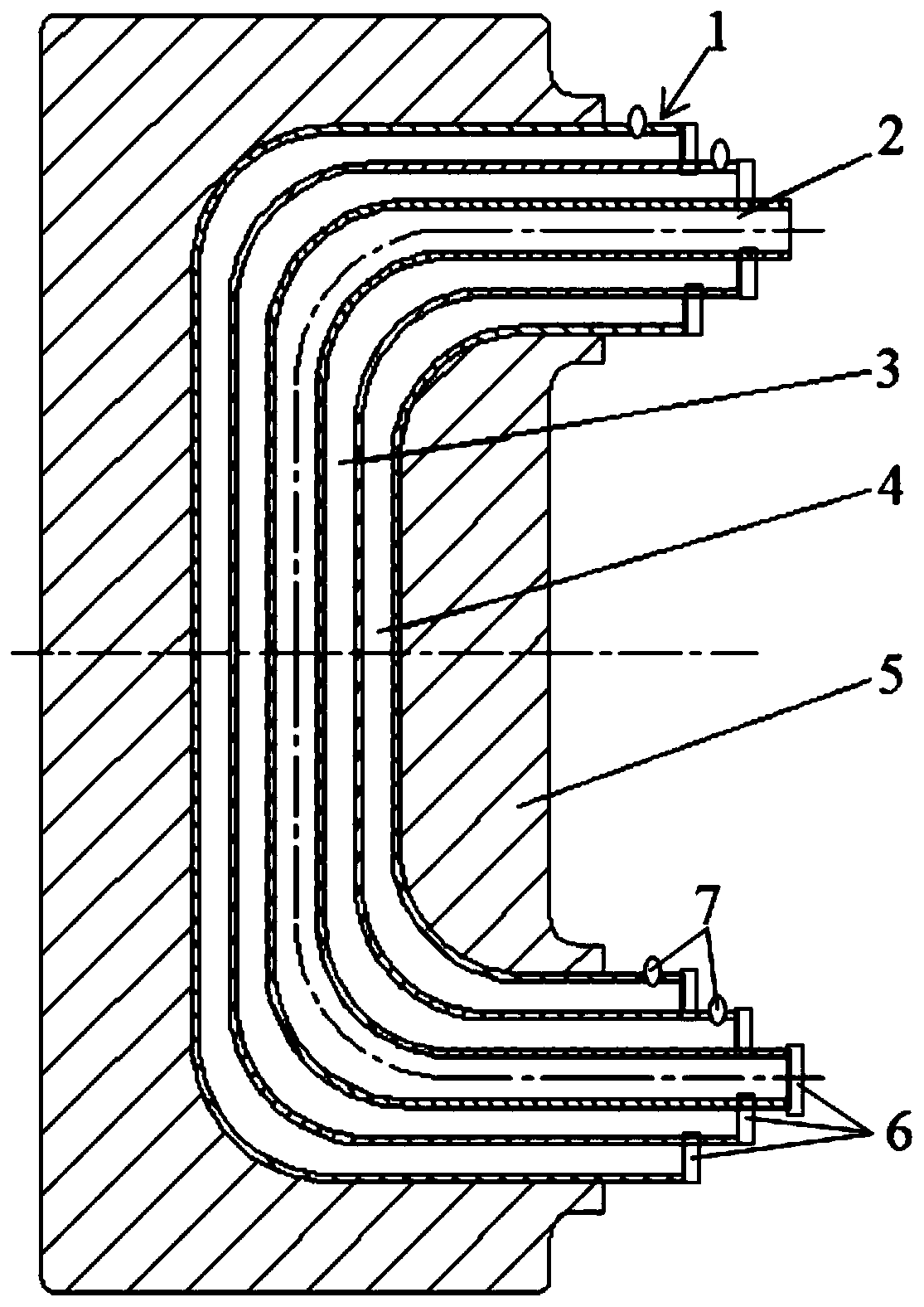
[0029] like figure 1 As shown, a water-saving multi-layer water supply tube blast furnace stave structure includes a furnace shell, a refractory lining and a cooling stave 5, the stave 5 is located between the furnace shell and the refractory lining, and cooling water pipes are arr...


PUM


Abstract

The invention discloses a water-saving blast furnace cooling wall structure with multiple layers of water supply pipes. The water-saving blast furnace cooling wall structure comprises a furnace shell,a refractory material lining and a cooling wall, wherein the cooling wall is located between the furnace shell and the refractory material lining; cooling water pipes are arranged in the cooling wall; the cooling water pipes are of a multi-layer water pipe structure; multiple layers of water pipes are of a nested structure; the cooling water pipes comprise an inner-layer water pipe; the water passing amount of the inner-layer water pipe 2 is larger than or equal to 30 percent of a water amount required by blast furnace cooling strength; end parts of the multiple layers of water pipes are arranged in a stepped way; and distances between the end parts of the multiple layers of water pipes are larger than or equal to 30 mm, so as to meet the field construction requirement for rapid switchingof the water pipes. The cooling water pipes are designed into the multi-layer water pipe structure, so that the guarantee requirement that each water supply point on the blast furnace cooling wall can always supply water safely for a plurality of times is met; and after water supply pipes at each water supply point of the blast furnace cooling wall are damaged, standby water pipes can be switchedrepeatedly to keep stable water supply for cooling. The invention further discloses an application process of the water-saving blast furnace cooling wall structure with multiple layers of water supply pipes.

Description

technical field [0001] The invention belongs to the technical field of blast furnace smelting, and in particular relates to a water-saving multilayer water supply pipe blast furnace stave structure and an application process thereof. Background technique [0002] The blast furnace stave is an important cooling equipment for the blast furnace body; the shell of the blast furnace body is usually made of BB503 hot-rolled steel plate with a thickness of 20-100 mm, and the shell is lined with refractory bricks. In order to protect the stability of the furnace shell, a cooling wall is installed between the furnace shell and the refractory lining, and the cooling water is passed through for cooling to protect the strength and rigidity of the furnace shell and realize the safety and stability of the furnace body during production and operation. [0003] There are a large number of large blast furnace staves, about 1,000 cooling staves are installed on the furnace shell to ensure tha...

Claims


Application Information

Patent Timeline
Patent Type & Authority Applications(China)
IPC IPC(8): C21B7/10
CPCC21B7/10
Inventor 廖海欧赵岚赵岩江济
Owner MAANSHAN IRON & STEEL CO LTD
Learn More