
Piezoelectric ink-jet printing device with outer surface electrode layer

一种喷墨打印、器件的技术

Pending Publication Date: 2020-07-24
SUZHOU RUIFA PRINTING TECH CO LTD
View PDF4 Cites 4 Cited by
  • Summary
  • Abstract
  • Description
  • Claims
  • Application Information

AI Technical Summary

Problems solved by technology

Individual piezoelectric plates for each droplet ejector make it difficult to fabricate large arrays of closely spaced droplet ejectors

Method used


Image

  • Piezoelectric ink-jet printing device with outer surface electrode layer
  • Piezoelectric ink-jet printing device with outer surface electrode layer
  • Piezoelectric ink-jet printing device with outer surface electrode layer

Examples


Embodiment Construction

[0025] The present invention includes various combinations of the embodiments described herein. References to "specific embodiments" and the like refer to features present in at least one embodiment of the invention. Separate references to "one embodiment" or "a particular embodiment" and the like do not necessarily refer to the same embodiment or embodiments; however, unless explicitly indicated or obvious to those skilled in the art, these embodiments are not Mutually exclusive. When referring to "one method" or "multiple methods" and similar terms, the use of the singular or plural number is non-limiting. It is specifically noted that the use of "or" has no exclusive meaning in this article unless it is clearly indicated otherwise or required by the context. Words such as "above", "below", "above" or "below" are intended to describe the gap between features located in different planes Positional relationship, but it should be understood that in a device orientation, the f...


PUM


Abstract

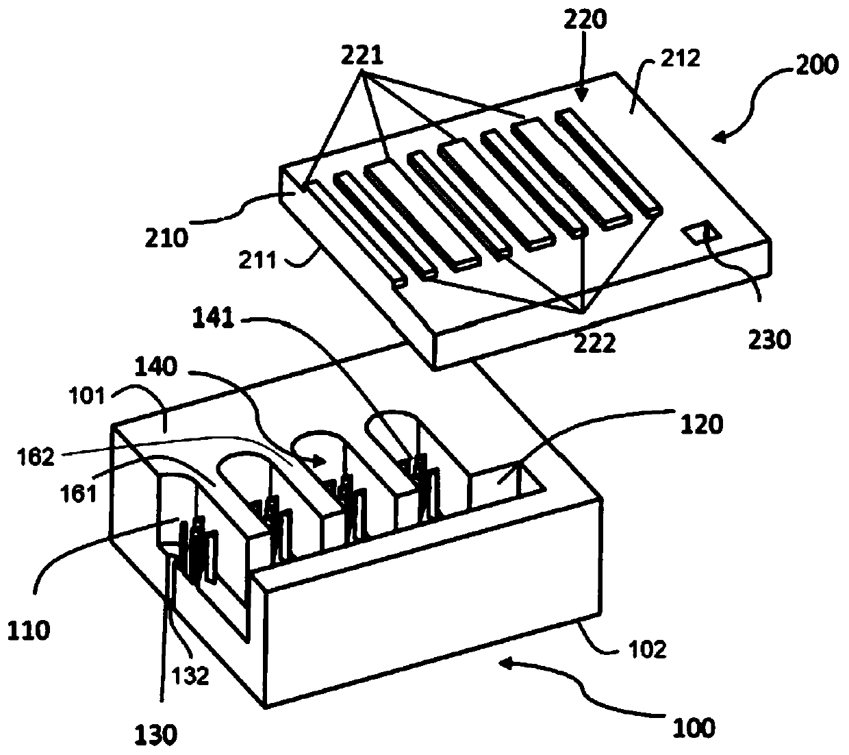
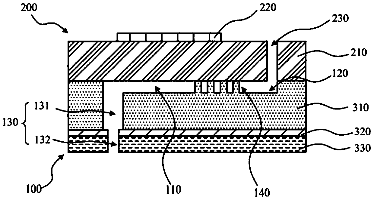
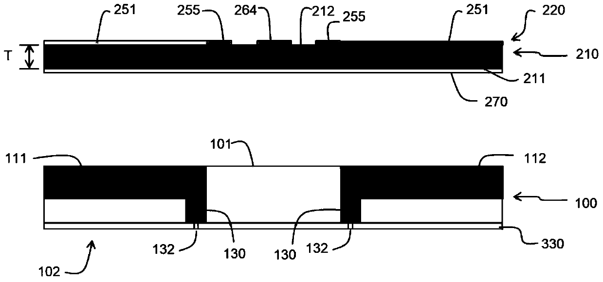
A piezoelectric ink-jet printing device comprises a base plate and a piezoelectric plate. A pair of liquid drop injector rows arranged in a staggered mode are arranged on the base plate in the arranging direction. Each liquid drop injector comprises a spray hole connected with pressure chamber liquid, and a pressure chamber is defined by a side wall. A first surface of the piezoelectric plate closely abuts against the pressure chambers. An electrode layer is arranged on the second outer surface, opposite to the first surface, of the piezoelectric plate. The electrode layer comprises signal lines corresponding to the liquid drop injectors in the staggered rows, and at least one public main ground electrode, and the public main ground electrodes are connected to ground electrodes which are located on the upper portions of the pressure chambers and are aligned along the side wall. Each signal line is connected to a corresponding signal input welding disc arranged between the staggered rows. The public main ground electrodes extend in the arranging direction and are connected to a return welding disc.

Description

Technical field [0001] The invention belongs to the field of piezoelectric inkjet printing, and more specifically, relates to the structure of a piezoelectric inkjet printing device. Background technique [0002] Inkjet printing is usually done with drop-on-demand inkjet or continuous inkjet printing. In drop-on-demand inkjet printing, droplets are ejected onto the recording medium using a droplet ejector with a booster (such as thermal or piezoelectric) actuator. Selective activation of the driver causes the formation and ejection of a flying ink drop that passes through the space between the print head and the recording medium and strikes the recording medium. The formation of the printed image is achieved by controlling the formation of each droplet in accordance with the needs of the required image for printing. The desired image may include any dot pattern corresponding to the image data. It can include graphics or text images. If appropriate ink is used, it can also inc...

Claims


Application Information

Patent Timeline
Patent Type & Authority Applications(China)
IPC IPC(8): B41J2/14B41J2/045
CPCB41J2/14201B41J2/04501B41J2/14233B41J2002/14403B41J2002/14491B41J2/045
Inventor 谢永林张小飞吕慧强陆建斌杜旋
Owner SUZHOU RUIFA PRINTING TECH CO LTD
Learn More