
Band-gap reference circuit

A technology of reference circuit and compensation circuit, applied in the field of microelectronics, can solve the problem that the voltage source cannot meet the accuracy requirements of system-level modules, and achieve the effect of good accuracy requirements, low temperature coefficient, and high temperature range

Active Publication Date: 2020-07-17
INST OF MICROELECTRONICS CHINESE ACAD OF SCI
View PDF4 Cites 9 Cited by
  • Summary
  • Abstract
  • Description
  • Claims
  • Application Information

AI Technical Summary

Problems solved by technology

[0010] In view of this, the embodiment of the present application provides a bandgap reference circuit, which can solve the problem that the voltage source generated by the traditional bandgap reference circuit in the prior art cannot meet the accuracy requirements of the system-level modules in modern analog integrated circuits, and provides a A Bandgap Reference Circuit with Wide Temperature Range and Low Temperature Coefficient

Method used


Image

  • Band-gap reference circuit
  • Band-gap reference circuit
  • Band-gap reference circuit

Examples


Embodiment Construction

[0070] In order to enable those skilled in the art to better understand the solution of the present application, the technical solution in the embodiment of the application will be clearly and completely described below in conjunction with the accompanying drawings in the embodiment of the application. Obviously, the described embodiment is only It is a part of the embodiments of this application, not all of them. Based on the embodiments in this application, all other embodiments obtained by persons of ordinary skill in the art without making creative efforts belong to the scope of protection of this application.

[0071] At present, the BE junction voltage with negative temperature characteristics and ΔVbe with positive temperature characteristics can be added together with appropriate weights to perform first-order temperature compensation, thereby obtaining a temperature-independent reference voltage, the reference voltage V ref Can refer to formula (1), where, let V ref ...


PUM


Abstract

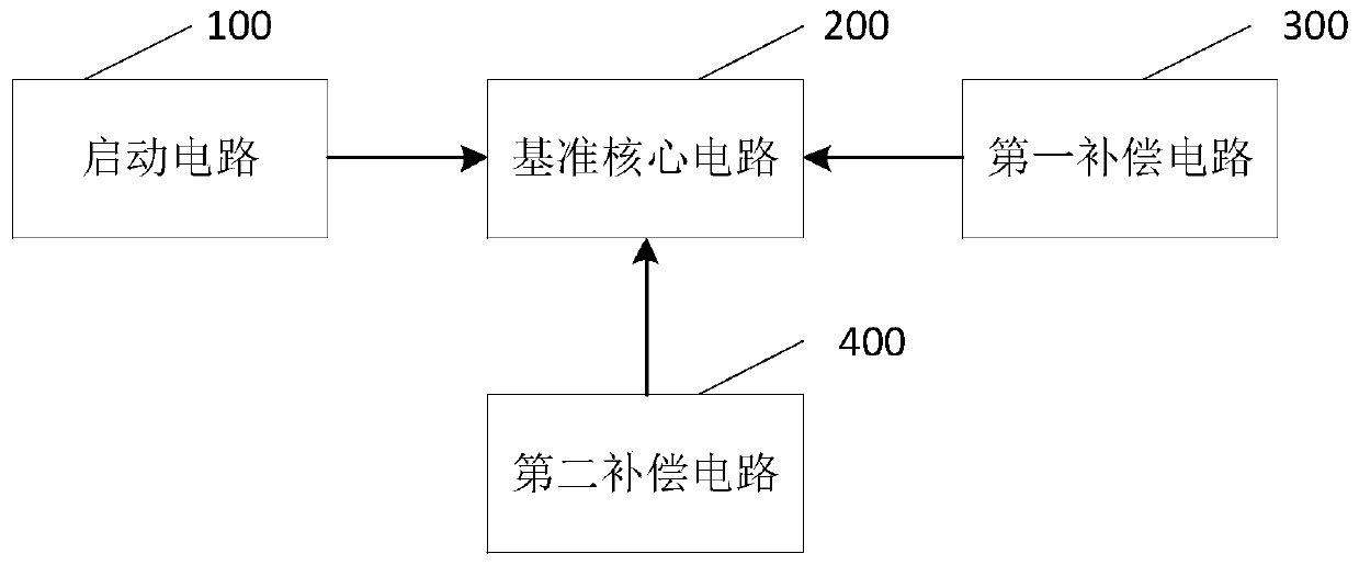
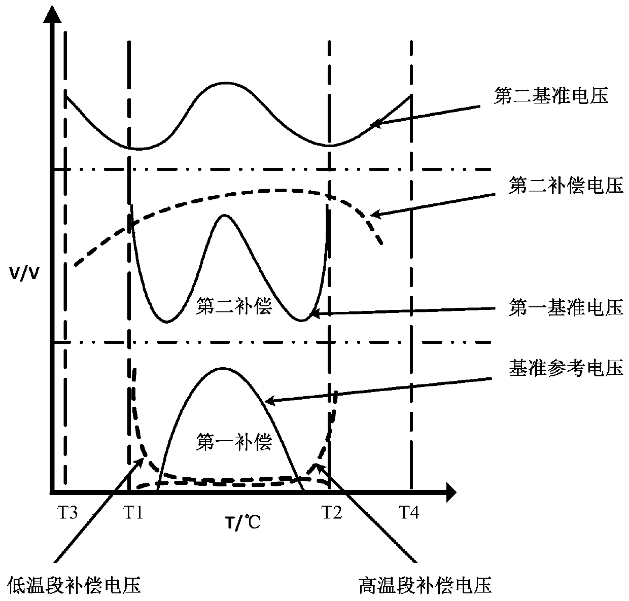
The embodiment of the invention discloses a band-gap reference circuit. The circuit comprises a core circuit, a first compensation circuit and a second compensation circuit. The core circuit is used for generating band-gap reference voltage; the first compensation circuit is used for generating a first compensation current by utilizing the temperature characteristic of a MOS transistor in a sub-threshold region and carrying out first compensation on the band-gap reference voltage; the second compensation circuit is used for generating a second compensation current by utilizing the characteristic of the difference between the BE junction voltages of two bipolar transistors and carrying out second compensation on the band-gap reference voltage. The band-gap reference voltage can be compensated from different angles through the first compensation current and the second compensation current, so that the high-order temperature coefficient in the band-gap reference voltage is effectively compensated, and the band-gap reference voltage obtained after compensation has the characteristics of high temperature range, low temperature coefficient and high precision.

Description

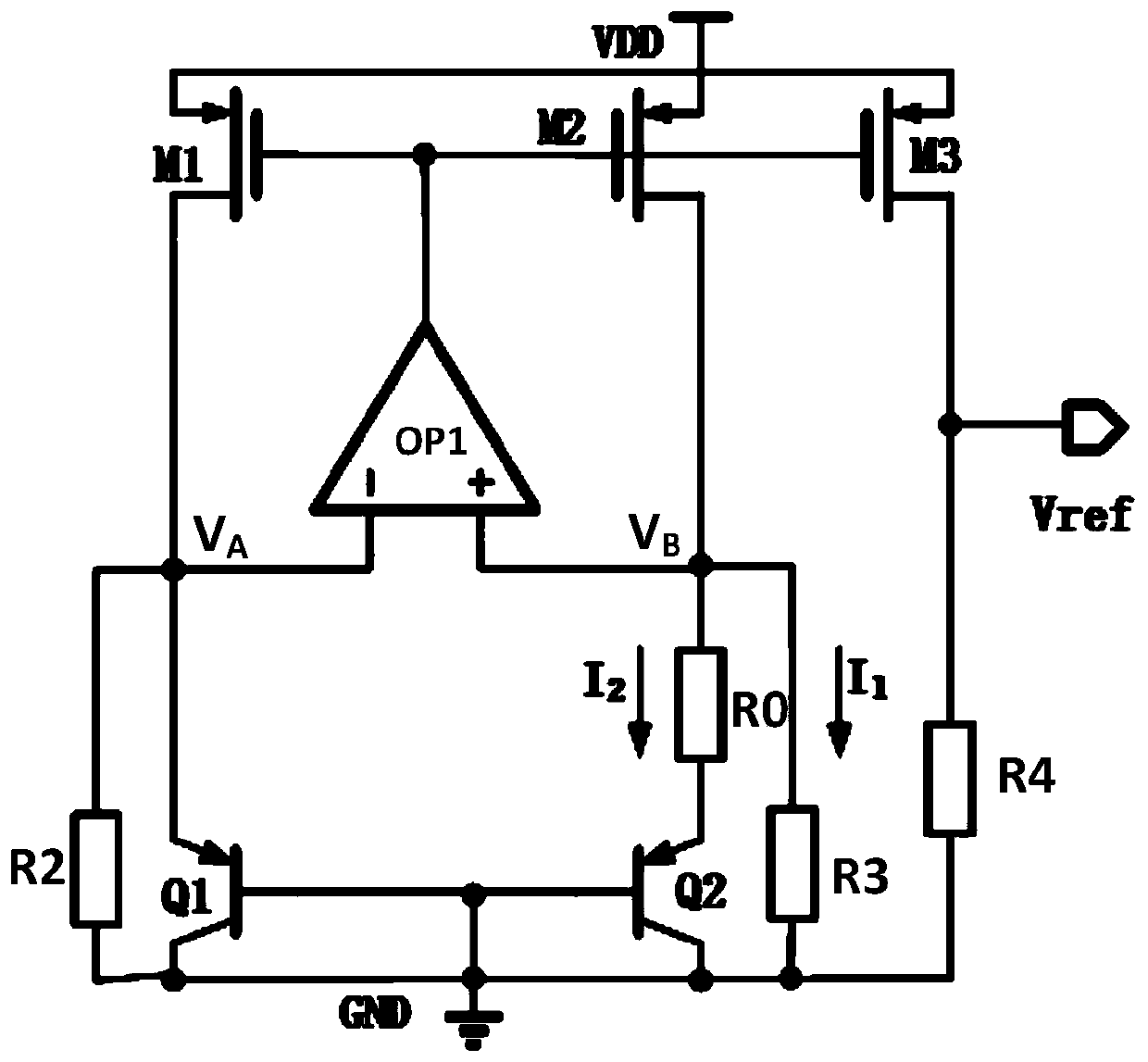
technical field [0001] The present application relates to the technical field of microelectronics, in particular to a bandgap reference circuit. Background technique [0002] Bandgap Reference (BGR) is an important module of modern analog integrated circuits and digital-analog hybrid integrated circuits. It is generally used in the fields of digital-to-analog converters and analog-to-digital converters, mobile device power management systems, and radio frequency circuits. The performance characteristics of the bandgap reference circuit directly affect the performance of the entire circuit, which requires improving the performance characteristics of the bandgap reference circuit. [0003] refer to figure 1 As shown, it is a schematic diagram of a traditional bandgap reference circuit, including PMOS transistors M1, M2, M3, operational amplifier OP1, bipolar transistors Q1, Q2, resistors R0, R2, R3, R4. The bandgap reference circuit uses two A negative temperature coefficien...

Claims


Application Information

Patent Timeline
Patent Type & Authority Applications(China)
IPC IPC(8): G05F1/567
CPCG05F1/567
Inventor 王颀陈腾刘飞霍宗亮
Owner INST OF MICROELECTRONICS CHINESE ACAD OF SCI
Learn More