
Piston valve type energy accumulator

A piston valve and accumulator technology, applied in the hydraulic field, can solve problems such as inconvenient replacement, system failure, and difficult maintenance, and achieve the effects of easy maintenance and replacement, low precision requirements, and reduced production costs

Pending Publication Date: 2020-07-17
杨世祥
View PDF0 Cites 2 Cited by
  • Summary
  • Abstract
  • Description
  • Claims
  • Application Information

AI Technical Summary

Problems solved by technology

[0003] 1. The sealing ring 121 frequently rubs against the inner wall of the cylinder 110 for a long time, which is easy to be damaged, causing the piston to sink to the bottom, resulting in a short service life of the accumulator 100 as a whole;
[0004] 2. After the sealing ring 121 is damaged, the compressed high-pressure gas easily enters the lower chamber 140, and enters the system through the high-pressure oil pipe 160 as the piston 120 moves down, causing system failure;
[0005] 3. The sealing ring 121 is located inside the cylinder 110. On the one hand, it is not conducive to the staff not to be able to find its damaged state in time. On the other hand, even if it is found to be damaged, it is not easy to replace, resulting in difficult maintenance;
[0006] 4. Since the sealing ring 121 is in close contact with the cylinder 110, the friction between the sealing ring and the inner wall of the cylinder needs to be overcome first in order to move the piston 120, so that the response speed of the accumulator 110 is slow

Method used


Image

  • Piston valve type energy accumulator
  • Piston valve type energy accumulator
  • Piston valve type energy accumulator

Examples


Embodiment 200

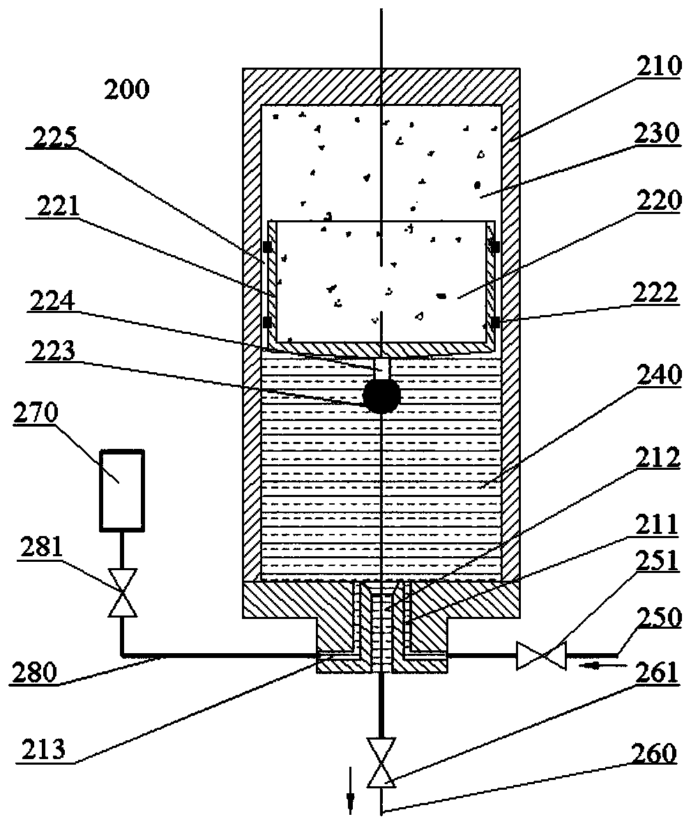
[0037] Such as Figure 2-3 As shown, an embodiment 200 of a piston valve accumulator according to the present invention generally includes a cylinder 210 and a piston valve 220 suspended within the cylinder 210 . Specifically, the space inside the cylinder 210 is divided into an upper chamber 230 and a lower chamber 240 by the piston valve 220, wherein the upper chamber 230 is used to accommodate high-pressure gas with a lower mass, while the lower chamber 240 is used to accommodate The high-pressure oil with relatively high quality, the piston valve 220 is suspended in the cylinder 210 by the buoyancy of the high-pressure oil and moves up and down with the change of air pressure and oil pressure. The bottom of the lower chamber 240 is provided with an air filling port 211 connected to the high-pressure air pipe 250 and a high-pressure oil port 212 connected to the high-pressure oil pipe 260 . The high-pressure air pipe 250 is provided with an inflation valve 250, which can b...


PUM


Abstract

The invention discloses a piston valve type energy accumulator. The piston valve type energy accumulator comprises a cylinder barrel and a piston valve, wherein the piston valve is suspended in the cylinder barrel; the cylinder barrel is divided into an upper chamber for accommodating high-pressure gas and a lower chamber for accommodating high-pressure oil by the piston valve; and a gas charginghole connected to a high-pressure gas tube and a high-pressure oil hole connected to a high-pressure oil tube are formed in the bottom of the lower chamber. The piston valve type energy accumulator does not use a sealing ring, and effectively overcomes the defects that the service life is short as the sealing ring is damaged, the piston sinks, gas enters a pipeline, system faults are liable to cause, and maintenance difficulty is great, and the like.

Description

technical field [0001] The invention relates to the technical field of hydraulic pressure, in particular to a piston valve type accumulator. Background technique [0002] The accumulator is an energy storage device in the hydraulic system. Its function is to store the excess energy in the system at an appropriate time, and release the stored energy when the system needs it, and re-supply the system. The piston accumulator is a form of accumulator commonly used in the prior art, such as Figure 1-2 As shown, the cylinder 110 is divided into an upper chamber 130 for containing high-pressure gas and a lower chamber 140 for containing high-pressure oil by a piston 120 located therein. Wherein, the top of the upper chamber 130 is provided with an inflation port 111 connected to the high-pressure air pipe 150, and the replenishment of high-pressure gas in the upper chamber 130 is realized by adjusting the inflation valve 151 provided on the high-pressure air pipe 150; the bottom o...

Claims


Application Information

Patent Timeline
Patent Type & Authority Applications(China)
IPC IPC(8): F15B1/24F15B1/22F15B1/04F15B19/00F15B20/00
CPCF15B1/24F15B1/22F15B1/04F15B19/00F15B20/005F15B2201/312F15B2201/4155F15B2201/50F15B2201/51F15B2201/405
Inventor 杨世祥
Owner 杨世祥
Learn More