Building high-altitude scaffold erection connecting piece
A technology for scaffolding and construction, which is applied in the connection of scaffolding, construction, building construction, etc., can solve problems such as insecurity and inconvenient installation, and achieve the effect of safe installation, simple structure, and convenience for later demolition
- Summary
- Abstract
- Description
- Claims
- Application Information
AI Technical Summary
Problems solved by technology
Method used
Image


Examples
Embodiment 1
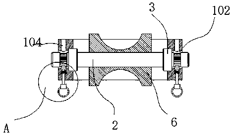
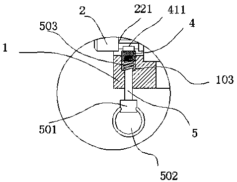
[0031] refer to Figure 1 to Figure 6The shown one kind of high-altitude scaffolding construction connector for construction includes two square clamps 1 arranged symmetrically up and down. The left and right sides of the square clamps 1 are processed with ear plates 101. Bolts 121 are fitted between the hoops 1 through the ear plates 101, and a rotating shaft 2 is arranged inside each of the square hoops 1, and the side walls of the square hoops 1 are processed with the shafts 2 for matching assembly. The assembly hole 102 is used, the assembly hole 102 is a stepped hole, a bearing 3 is fitted between the transfer hole 102 and the rotating shaft 2, and the bearing 3 is installed at the large hole position of the assembly hole 102. The front end face of the square clamp 1 is provided with a first assembly hole 103, and the first assembly hole 103 is also a stepped hole, and the rear end surface of the square clamp 1 is provided with a hole corresponding to the first assembly h...
Embodiment 2
[0037] refer to Figure 7 As shown, a plurality of anti-slip ribs 661 are formed by injection molding in the annular groove 601, and an arc-shaped notch groove 662 is formed by injection molding on the outside of the anti-slip ribs 661. When the upper and lower square clamps 1 are tightened, the anti-slip Rib 661 fits the scaffold steel pipe after deformation, and now the rotation resistance of rotating shaft 2 increases; the above-mentioned structure can increase the frictional resistance with the scaffold steel pipe 9 through the deformation of anti-slip rib 661. Only when the strength is high, the positioning tube 6 can be driven to rotate. At this time, even if the connection between the positioning pin 411 and the tooth groove 221 fails, it can remain stable.
Embodiment 3
[0039] refer to Figure 8 , Figure 9 and Figure 10 As shown, a locking screw 8 is screwed into the outside of the circular clamp 7, the lower end of the locking screw 8 is processed to form a ball head 801, and the outer wall of the locking screw 8 is radially close to the upper end position. A plurality of force-bearing holes 802 are provided through; two scaffold steel pipes 9 docked in the circular clamp 7 are equipped with inserts 10, the diameter of the inserts 10 is greater than the inner diameter of the scaffold steel pipe 9, and the inserts The block 10 has an intubation part 11, which is inserted into the steel pipe 9 of the scaffold, and is transitionally fitted with it. The insertion block 10 has an outer conical surface 12, and the ball head 801 acts on the outer conical surface 12. Above, when the locking screw 8 is screwed down, the inserting blocks 10 on both sides are pushed away, and at this time, the cooperation resistance between the inserting block 10 a...
PUM
 Abstract
Description
Claims
Application Information
 - Generate Ideas
- Intellectual Property
- Life Sciences
- Materials
- Tech Scout
- Unparalleled Data Quality
- Higher Quality Content
- 60% Fewer Hallucinations
Browse by: Latest US Patents, China's latest patents, Technical Efficacy Thesaurus, Application Domain, Technology Topic, Popular Technical Reports.
© 2025 PatSnap. All rights reserved.Legal|Privacy policy|Modern Slavery Act Transparency Statement|Sitemap|About US| Contact US: help@patsnap.com