Rear suspension line lower adjusting tool structure

A technology for adjusting tooling and hanging wires, which is applied in the field of adjusting tooling structures under the rear suspension wires, can solve the problems of increasing the cost of detection line equipment, complicated manufacturing, and good vehicle comfort, so as to improve the assembly accuracy of the rear suspension and reduce the equipment cost. Cost, the effect of reducing the transformation cost

Pending Publication Date: 2020-07-17
IAT AUTOMOBILE TECH
View PDF0 Cites 2 Cited by
  • Summary
  • Abstract
  • Description
  • Claims
  • Application Information

AI Technical Summary

Problems solved by technology

The existing automotive rear suspension structures mainly include torsion beam and multi-link. The torsion beam structure is low in cost and simple to manufacture, but poor in vehicle comfort. The multi-link structure is high in cost and complicated in manufacture, but good in vehicle comfort. Now more and more models adopt multi-link structure
[0003] In the prior art, the rear suspension structures of automobiles mainly include torsion beam and multi-link. The adjustment of the rear wheel toe-in can meet the design parameters of the whole vehicle, which increases the equipment cost of the inspection line, especially some inspection lines that cannot be adjusted for rear wheel camber and rear wheel toe-in. The inspection line transformation cost reduces the adjustment efficiency of the inspection line
As users have higher and higher requirements for the comfort of the vehicle, the layout of the vehicle is becoming more and more complex. Many models have no tool adjustment space after the vehicle is assembled, and online adjustment cannot be realized.

Method used


Image

  • Rear suspension line lower adjusting tool structure
  • Rear suspension line lower adjusting tool structure
  • Rear suspension line lower adjusting tool structure

Examples


Embodiment Construction

[0027] The structure of the rear under-suspension adjustment tool of the present invention will be further described below in conjunction with specific embodiments, so as to help those skilled in the art have a more complete, accurate and in-depth understanding of the inventive concepts and technical solutions of the present invention.

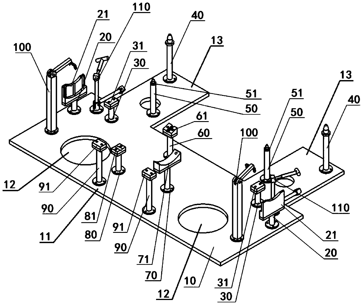
[0028] This embodiment provides a rear suspension adjustment tooling structure, such as figure 1 As shown, it includes a base plate 10, the base plate 10 has an axisymmetric structure, it includes a base plate main body 11 and a pair of extension plates 13 symmetrically arranged on both sides of the rear end of the base plate main body 11, and the base plate main body 11 is provided with Through hole 12. A pair of rear sub-frame auxiliary support structures 90 are symmetrically arranged on both sides of the front middle part of the base plate main body 11, and a pair of rear camber positioning structures 100 are symmetrically arranged on both ...


PUM


Abstract

The invention relates to a rear suspension line lower adjusting tool structure, which belongs to the technical field of automobile production and manufacturing. The rear suspension line lower adjusting tool structure comprises a rear auxiliary frame positioning pin structure, a rear auxiliary frame auxiliary supporting structure, a rear brake disc supporting structure, a swing arm supporting structure, a swing arm supporting structure, a motor supporting structure, a rear wheel toe-in positioning structure, a rear wheel camber angle positioning structure and a vehicle body assembling positioning structure which are arranged on a base plate. The rear suspension line lower adjusting tool structure is a tool structure integrating rear suspension sub-assembly, rear suspension combined assemblyand rear suspension adjustment, what is guaranteed is that the camber angle and toe-in of the rear wheel are consistent with the design state and are assembled in place at a time by designing a positioning structure on the tool, and the procedure of adjusting the camber angle and toe-in of the rear wheel on a detection line is omitted.

Description

technical field [0001] The invention relates to the technical field of automobile production and manufacturing, and more specifically, the invention relates to a tooling structure for adjusting the rear suspension under the wire. Background technique [0002] With the continuous progress of society and the continuous improvement of people's living standards, cars have entered thousands of households and become an indispensable means of transportation for people's daily life. The existing automotive rear suspension structures mainly include torsion beam and multi-link. The torsion beam structure is low in cost and simple to manufacture, but poor in vehicle comfort. The multi-link structure is high in cost and complicated in manufacture, but good in vehicle comfort. Now more and more models adopt multi-link structure. [0003] In the prior art, the rear suspension structures of automobiles mainly include torsion beam and multi-link. The adjustment of the rear wheel toe-in ca...

Claims


Application Information

Patent Timeline
Patent Type & Authority Applications(China)
IPC IPC(8): B62D65/12B62D65/00
CPCB62D65/00B62D65/12
Inventor 常建伟冷红江岳张锋
Owner IAT AUTOMOBILE TECH
Why Eureka
Try Eureka