Multi-direction dust removal equipment for instruments and apparatuses
A technology for instrumentation and dust removal equipment, which is applied in the field of multi-directional dust removal equipment for instruments and meters. It can solve problems such as small dust removal range, aging of components, and influence on circuit heat dissipation, and achieve the effect of improving dust removal efficiency and expanding the scope and direction
- Summary
- Abstract
- Description
- Claims
- Application Information
AI Technical Summary
Problems solved by technology
Method used
Image
Examples
Embodiment 1
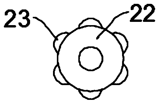
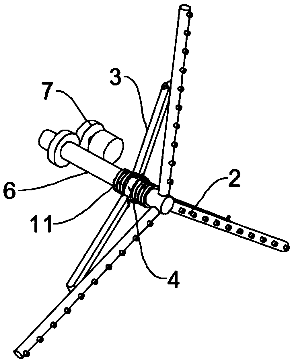
[0026] see Figure 1~3 , in an embodiment of the present invention, a multi-directional dust removal equipment for instruments and meters includes a box body 1 and a dust removal unit. The bottom of the box body 1 is evenly and symmetrically fixed with rollers to facilitate the movement of the device. A side wall of the box body 1 is installed with The box door, in the present embodiment, the box door is preferably installed on the box body 1 by hinges and hasps, and at least one exhaust fan 10 for extracting dust in the box body 1 is installed on the top of the box body 1, and the box body 1 is provided with a screen frame 8 for placing instruments and meters. The top of the screen frame 8 is connected to the top of the inner cavity of the box body 1 through a plurality of slings 9. The dust removal unit includes a side dust removal assembly and a lower dust removal assembly. The dust removal assembly includes a first hollow rotating shaft 6, a first drive mechanism 7 that dr...
Embodiment 2
[0029] see Figure 4The difference between this embodiment of the present invention and Embodiment 1 is that the top of the second hollow rotating shaft 13 is horizontally threaded with a first threaded rod 19, one end of the first threaded rod 19 is threaded with a second threaded rod 20, and The tops of the two threaded rods 20 are in contact with the bottom of the screen frame 8. In this embodiment, the second threaded rods 20 are connected with the fixed mounting threaded sleeves 21 at the ends of the first threaded rods 19, and the second threaded rods are adjusted by the first threaded rods 19. The contact position between the rod 20 and the bottom of the screen frame 8 adjusts the inclination of the screen frame 8 through the second threaded rod 20. When the second hollow shaft 13 rotates, it drives the first threaded rod 19 and the second threaded rod 20 to rotate, and the second threaded rod 19 and the second threaded rod 20 rotate. The rod 20 drives the screen frame ...
PUM
 Abstract
Description
Claims
Application Information
 - Generate Ideas
- Intellectual Property
- Life Sciences
- Materials
- Tech Scout
- Unparalleled Data Quality
- Higher Quality Content
- 60% Fewer Hallucinations
Browse by: Latest US Patents, China's latest patents, Technical Efficacy Thesaurus, Application Domain, Technology Topic, Popular Technical Reports.
© 2025 PatSnap. All rights reserved.Legal|Privacy policy|Modern Slavery Act Transparency Statement|Sitemap|About US| Contact US: help@patsnap.com


