
Power device for spraying paint

A technology of power device and movable frame, which is applied in the direction of injection device, etc., to achieve the effect of exquisite design and compact structure

Pending Publication Date: 2020-07-17
SICHUAN GUORUAN SCI & TECH DEV CO LTD
View PDF0 Cites 0 Cited by
  • Summary
  • Abstract
  • Description
  • Claims
  • Application Information

AI Technical Summary

Problems solved by technology

[0003] In the prior art, an automatic painting device (such as a robot, etc.) is usually used to paint articles (or called workpieces), and the automatic painting device is usually set in a relatively closed painting space, such as a special painting room; The workpieces that need to be painted are usually set on the orientation control device that can adjust the orientation by rotation, and the orientation control device is connected with the conveying line so as to be sequentially transported to the painting station set in the painting space through the conveying line (such as chain conveying line, etc.) position; the orientation control device is provided with a joint for connecting the power device, and a paint spraying device for spraying paint and a power device for providing power for the orientation control device are usually required to be provided at the painting station. In some painting devices, when the azimuth control device moves to the painting station, the power device can be connected with the azimuth control device through the joint in the azimuth control device, so as to provide power for the rotation of the workpiece during the painting process, while the existing The power unit cannot meet the demand and needs to be improved urgently

Method used


Image

  • Power device for spraying paint
  • Power device for spraying paint
  • Power device for spraying paint

Examples


Embodiment 1

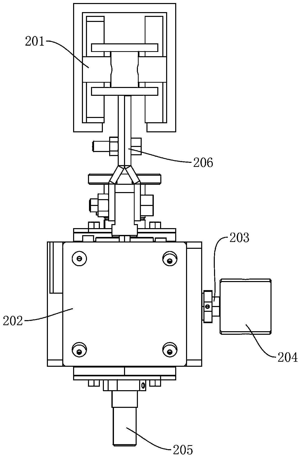
[0033] In the painting process, the workpiece that needs to be painted is usually arranged on an orientation control device 202 that can adjust the orientation of the workpiece by rotation. Conveying line 201, etc.) to be transported to the painting station that is arranged in the painting space successively; figure 1 As shown, the azimuth control device 202 is provided with a frame, one side of the frame is provided with a joint 203 for connecting the power device, and the lower end of the frame is provided with a hanger joint 205 connected to the workpiece hanger, and the joint 203 is connected to the The hanger joint 205 is connected through the power transmission mechanism arranged in the frame, and has a fixed transmission ratio. The orientation control device 202 can be moved to the painting station under the drive of the conveying line 201. , the joint 203 of the orientation control device 202 needs to be connected with the power device arranged at the painting station,...

Embodiment 2

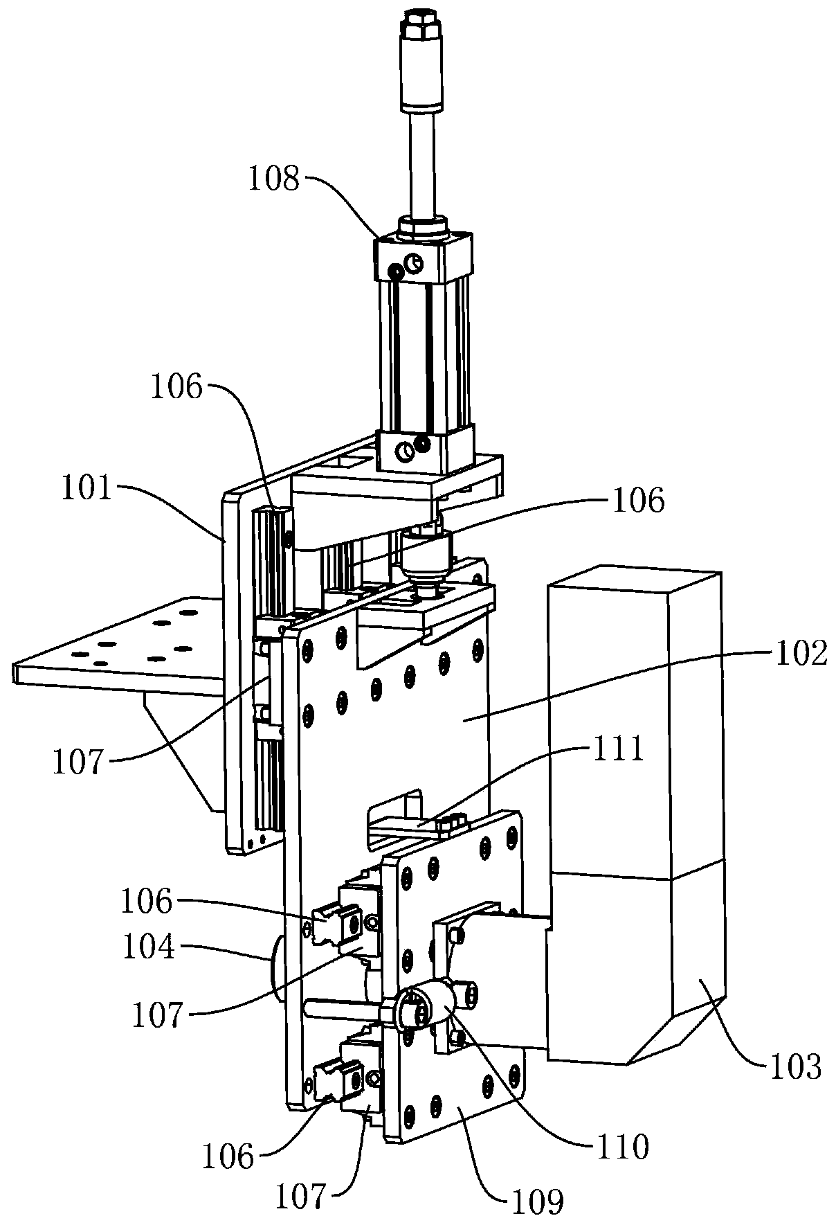
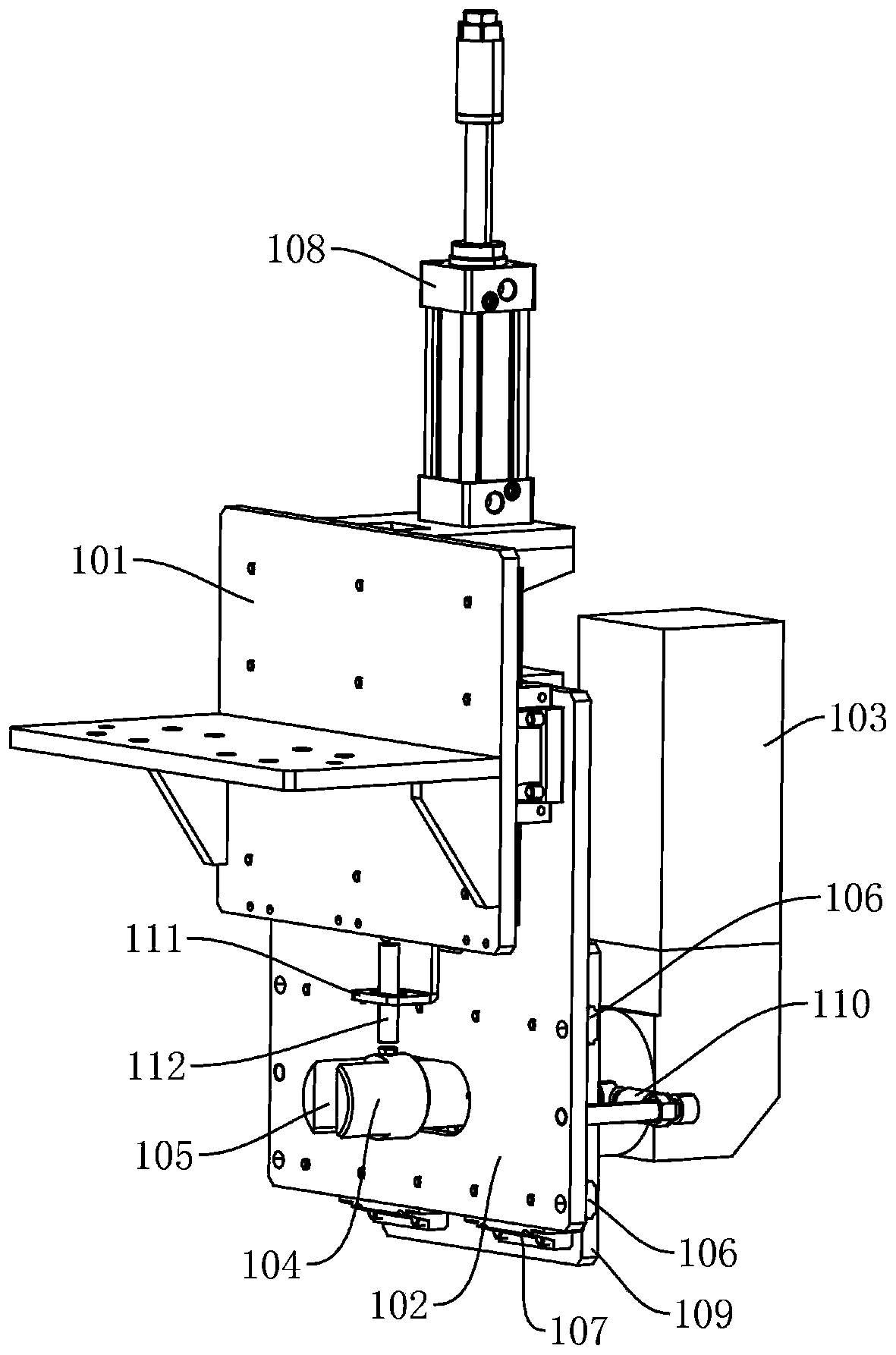
[0045] Since the connector 104 in the power unit and the joint 203 in the azimuth control device 202 are detachably connected, there must be a matching gap between the two, that is, there must be a gap between the card slot 105 and the connecting block 204; when the power unit After the connecting head 104 in the azimuth control device 202 is connected to the joint 203 in the azimuth control device 202, due to the fit gap between the connecting head 104 and the joint 203, the axes of the connecting head 104 and the joint 203 are not concentric, which is not conducive to transmission. In order to solve this problem, In the power device provided in this embodiment, it also includes a self-adjusting frame 109, such as Figure 2-Figure 5 As shown, the drive motor 103 is fixed on the self-adjusting frame 109, and the self-adjusting frame 109 is arranged on the movable frame 102 through the second linear module, and the second linear module and the first module perpendicular to each...

Embodiment 3

[0048] Because there is a matching gap between the connector 104 and the connector 203, when the connector 203 is driven by the power unit to rotate a circle and finish painting (return to the initial position), as Figure 7 As shown, at this time, the rotation angle of the connector 104 must be greater than 360 degrees, that is, the connector 104 is not at the initial position, as Figure 7 As shown, it is inconvenient for the connector 104 to cooperate with the connector 203 of the next orientation control device 202. To solve this problem, the power device provided in this embodiment also includes a sensor 112 and a controller. The connector 104 Circumferential direction is provided with detection part 113, and described sensor 112 and driving motor 103 are connected with described controller respectively, and described sensor 112 is fixed on described self-adjusting frame 109, as image 3 and Figure 8As shown, the bracket 111 is used to fix the self-adjusting frame 109 s...


PUM


Abstract

The invention relates to a power device for spraying paint. The power device comprises a fixed frame, a movable frame, a driving motor and a connector. The movable frame is arranged on the fixed frameand can move relative to the fixed frame. The driving motor is arranged on the movable frame, and the driving motor is used for driving the connector to rotate. The connector is matched with a jointin a direction control device. The power device for spraying the paint is compact in structure and ingenious in design, and is matched with the direction control device in a paint spraying process ina detachable connection manner, so that a workpiece arranged in the direction control device is driven to rotate; and in addition, the problem that the axis of the connector and the axis of the jointare not concentric and the problem that the connector cannot restore an initial position conveniently can be effectively solved, and therefore paint spraying work is completed precisely and efficiently at low cost.

Description

technical field [0001] The invention relates to the technical field of painting equipment, in particular to a power device for painting. Background technique [0002] Spray paint (or spray coating) is dispersed into uniform and fine mist droplets by means of pressure or centrifugal force through a spray gun or disc atomizer, and is applied to the surface of the object to be coated. It is widely used in industry. [0003] In the prior art, an automatic painting device (such as a robot, etc.) is usually used to paint articles (or called workpieces), and the automatic painting device is usually set in a relatively closed painting space, such as a special painting room; The workpieces that need to be painted are usually set on the orientation control device that can adjust the orientation by rotation, and the orientation control device is connected with the conveying line so as to be sequentially transported to the painting station set in the painting space through the conveying...

Claims


Application Information

Patent Timeline
IPC IPC(8): B05B13/02
CPCB05B13/0228
Inventor 翟大庆屈良基周宗林
Owner SICHUAN GUORUAN SCI & TECH DEV CO LTD
Learn More