Method and system for measuring topological charges and positive and negative values of partially coherent vortex beams

A vortex beam and measurement part technology, applied in the field of optical measurement, can solve the problems of cumbersome, harsh conditions, difficult operation, etc., to achieve the effect of improving the success rate, reducing the harsh requirements, and simplifying the measurement process

Active Publication Date: 2020-07-14
SUZHOU UNIV
View PDF4 Cites 4 Cited by
  • Summary
  • Abstract
  • Description
  • Claims
  • Application Information

AI Technical Summary

Problems solved by technology

Especially when the reference point is (0,0), the phase distribution presents a circular dislocation, and the singularity cannot be seen
In the experiment, the selection conditions of this off-axis reference point are very harsh. Only when a suitable reference point is found can a clear singularity be seen, and the selection of the reference point is related to factors such as the size of the beam. In the experiment, continuous debugging is required to ensure Finding a suitable reference point makes the conditions of the experiment very harsh and cumbersome, and it is very difficult to operate
At the same time, in this patent, it is necessary to calculate the complex coherence to obtain the positive and negative information of the topological charge, which makes the whole measurement process more cumbersome

Method used


Image

  • Method and system for measuring topological charges and positive and negative values of partially coherent vortex beams
  • Method and system for measuring topological charges and positive and negative values of partially coherent vortex beams
  • Method and system for measuring topological charges and positive and negative values of partially coherent vortex beams

Examples


Embodiment Construction

[0059] The present invention will be further described below in conjunction with drawings and specific embodiments, so that those skilled in the art can better understand the present invention and implement it, but the examples given are not as limitations of the present invention.

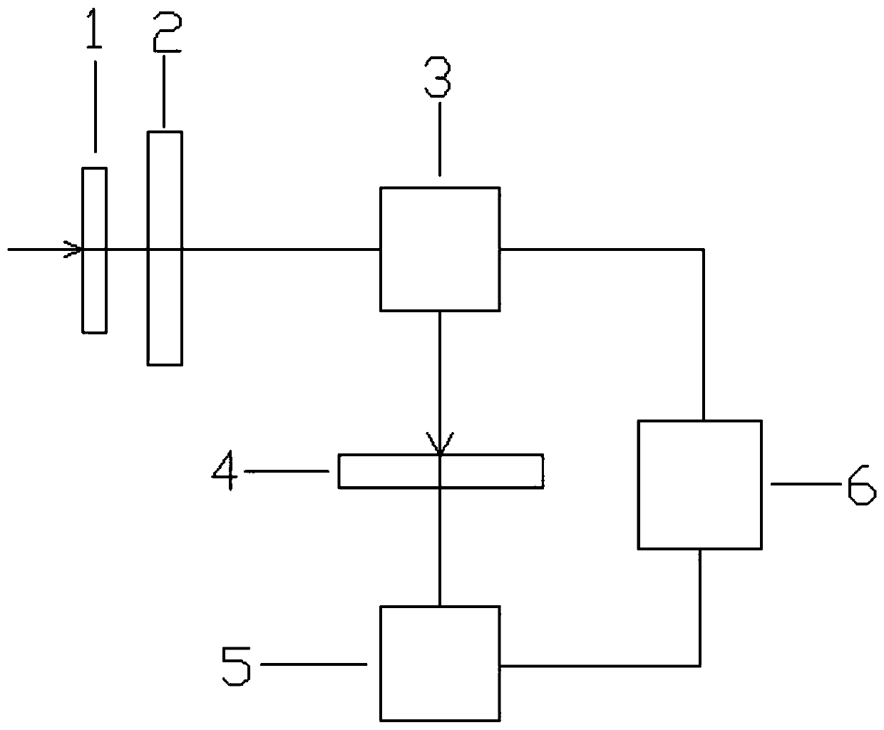
[0060] like figure 1 As shown, it is a method for measuring the topological charge of a partially coherent vortex beam according to an embodiment of the present invention, and the method includes the following steps:

[0061] Step S110, inject the partially coherent vortex beam into the double slit and interfere.

[0062] In one embodiment, the partially coherent vortex beam is generated by irradiating the partially coherent beam on a phase-only spatial light modulator loaded with a vortex phase.

[0063] Among them, the partially coherent vortex beam is incident on the double slit, and its cross spectral density expression is:

[0064]

[0065] where the double slit is next to the source pla...


PUM


Abstract

The invention discloses a method and a system for measuring topological charges and positive and negative values of partially coherent vortex light beams. The method comprises the following steps: enabling the partially coherent vortex light beams to enter double slits and generate interference; focusing the partially coherent vortex light beams after interference to a receiving screen of a pure phase spatial light modulator through a lens; introducing disturbance of three times of different phase assignment to the center of the partially coherent vortex light beams on the receiving screen through a pure phase spatial light modulator; carrying out fourier transform on the disturbed partially coherent vortex light beams, wherein the light intensity of a Fourier plane under three times of different phase assignment is recorded; according to the three times of different phase assignment and the light intensity of the Fourier plane under the three times of different phase assignment, basedon inverse Fourier transform, calculating to obtain a cross spectral density function of the partially coherent vortex beams after double-slit interference and focusing. Coherent singular points canbe directly observed from a phase distribution diagram of the cross spectral density function, and therefore the topological charges and positive and negative values of the partially coherent vortex beams are obtained.

Description

technical field [0001] The invention relates to the field of optical measurement, in particular to a method and system for measuring the magnitude and sign of the topological charge of a partially coherent vortex beam. Background technique [0002] A vortex beam that has a phase of exp , each photon of which carries an orbital angular momentum where l is the topological charge. Vortex beams have great application prospects in laser particle trapping, micromanipulation, information encoding, and optical information transmission. Therefore, the measurement of the topological charge of vortex beams is a very important work, which has unique advantages in laser processing, optical tweezers, and atom cooling. [0003] A singularity is a point in a light field where certain parameters cannot be defined. Under the condition of complete coherence, the light intensity at the center of the vortex beam is zero, the phase presents a spiral structure gradient, and the phase at the ...

Claims


Application Information

Patent Timeline
IPC IPC(8): G01J1/42G01J9/02
CPCG01J1/4257G01J9/02G01J2009/0211G01J2009/0249
Inventor 赵承良陈天池卢兴园蔡阳健
Owner SUZHOU UNIV
Why Eureka
Try Eureka