Gas guide structure and flow guide groove of gas compressor

A technology of air compressor and drainage tank, which is applied in the direction of mechanical equipment, engine components, machines/engines, etc., and can solve problems such as dangerous accidents, insufficient air supply flow or pressure, and increased airflow loss

Inactive Publication Date: 2020-07-14
AECC SHENYANG ENGINE RES INST
View PDF7 Cites 6 Cited by
  • Summary
  • Abstract
  • Description
  • Claims
  • Application Information

AI Technical Summary

Problems solved by technology

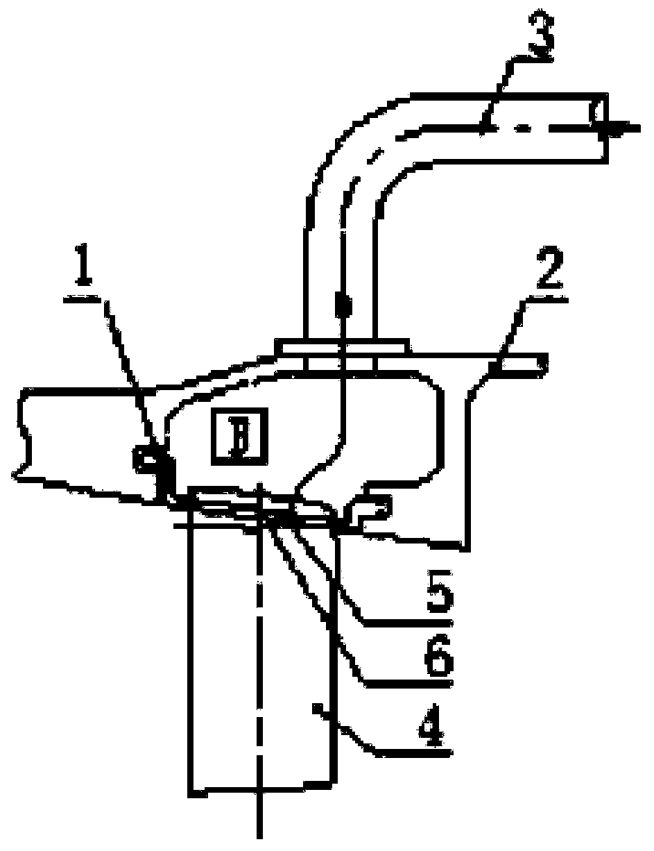
[0002] Air conditioning and pressurization in the cockpit, thermal anti-icing of wings, and cooling of hot-end parts of the engine often require an air source of appropriate temperature and pressure. Currently, this air source is mostly obtained from the engine compressor, and most of the solutions are in the compressor. The outer ring of the stator is located between two adjacent stator blades, and a circular or special-shaped air-introduction hole is provided, through which the airflow in the gas flow channel in the stator outer ring of the compressor is introduced to the space between the stator outer ring and the stator casing. Afterwards, the airflow entering the air collection chamber is led to the relevant parts of the aircraft cockpit, wing, and engine hot end parts through the bleed pipe, so as to serve as air conditioning and pressurization of the aircraft cabin, wing thermal anti-icing, engine The air source for cooling the hot end parts. In this technical scheme, when the air flow in the gas flow channel in the outer ring of the stator enters the gas collection cavity from the gas flow channel in the outer ring of the stator through circular or special-shaped air holes, there will usually be a large gap. The airflow turning angle increases the loss of airflow flow, which easily leads to insufficient air supply flow or pressure to the relevant parts of the aircraft cockpit, wings, and engine hot-end components, and it is difficult to meet the air conditioning and pressurization of the aircraft cockpit, wing thermal anti-icing, engine Cooling of hot-end components is required, which may lead to dangerous accidents in severe cases

Method used


Image

  • Gas guide structure and flow guide groove of gas compressor
  • Gas guide structure and flow guide groove of gas compressor
  • Gas guide structure and flow guide groove of gas compressor

Examples


Embodiment Construction

[0030] In order to make the technical solution of the present application and its advantages clearer, the technical solution of the present application will be further clearly and completely described in detail below in conjunction with the accompanying drawings. It can be understood that the specific embodiments described here are only part of the application Examples are only used to explain the present application, not to limit the present application. It should be noted that, for the convenience of description, only the parts related to the present application are shown in the drawings, and other relevant parts can refer to the general design. In the case of no conflict, the embodiments in the application and the technologies in the embodiments Features can be combined with each other to obtain new embodiments.

[0031] In addition, unless otherwise defined, the technical terms or scientific terms used in the description of the application shall have the usual meanings und...


PUM


Abstract

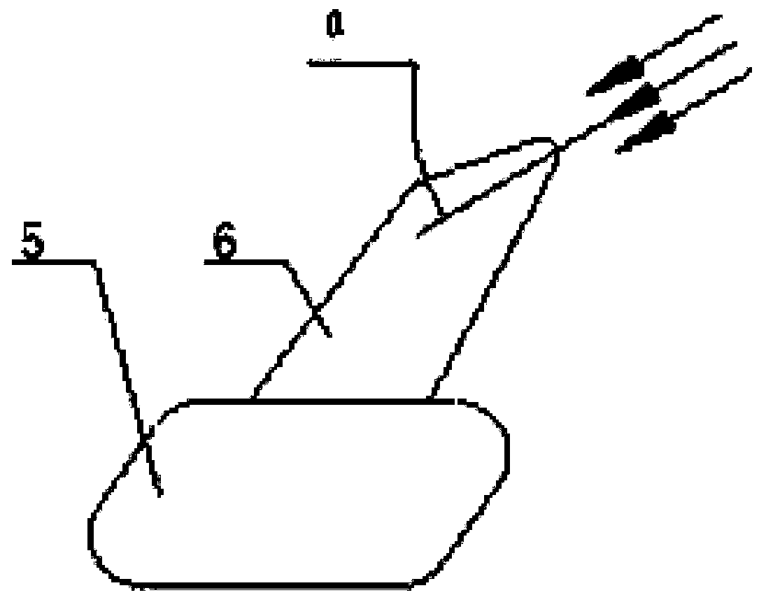
The invention belongs to the technical field of gas guide design of aircraft engines, and particularly relates to a gas guide structure of a gas compressor. The gas guide structure comprises a statorouter ring, a stator casing and a gas guide pipe, wherein the stator outer ring is provided with a gas guide hole, the inner side of the stator outer ring is provided with a flow guide groove, one endof the flow guide groove extends to the gas guide hole, the other end of the flow guide groove obliquely extends towards an incoming flow direction of an airflow channel in the stator outer ring, thestator outer ring is arranged in the stator casing, an air collection cavity communicating with the gas guide hole is formed between the stator casing and the stator outer ring, an air outlet hole communicating with the air collection cavity is formed in the stator casing, and an inlet of the gas guide pipe communicates with the air outlet hole. In addition, the invention further relates to a gascompressor flow guide groove which has all characteristics of the flow guide groove in the gas compressor gas guide structure.

Description

technical field [0001] The application belongs to the technical field of aircraft engine bleed air design, and in particular relates to a compressor bleed air structure and a drainage groove thereof. Background technique [0002] Air conditioning and pressurization in the cockpit, thermal anti-icing of wings, and cooling of hot-end parts of the engine often require air sources of appropriate temperature and pressure. The outer ring of the stator is located between two adjacent stator blades, and a circular or special-shaped air-introduction hole is provided, through which the airflow in the gas flow channel in the stator outer ring of the compressor is introduced to the space between the stator outer ring and the stator casing. Afterwards, the airflow entering the air collection chamber is led to the relevant parts of the aircraft cockpit, wing, and engine hot end parts through the bleed air pipe, so as to serve as air conditioning and pressurization of the aircraft cockpit,...

Claims


Application Information

Patent Timeline
Patent Type & Authority Applications(China)
IPC IPC(8): F04D29/40F01D9/04F01D25/24
CPCF01D9/041F01D25/24F04D29/403
Inventor 张岩蒋琇琇苗雨露
Owner AECC SHENYANG ENGINE RES INST
Why Eureka
Try Eureka