Fabric cutting and synthesizing system

A fabric and cutting device technology, which is applied to the cutting of textile materials, processing of textile material carriers, devices for coating liquid on the surface, etc., can solve the problems of high labor intensity for workers, affecting product quality, and inability to smooth fabrics, etc., to achieve Improve productivity and water spray quality, reduce labor intensity of workers, and overcome the effect of limited water spray range

Pending Publication Date: 2020-07-14
CENMOY AUTOMATION TECH SHANGHAI CO LTD
View PDF0 Cites 0 Cited by
  • Summary
  • Abstract
  • Description
  • Claims
  • Application Information

AI Technical Summary

Problems solved by technology

[0002] The existing fabric cutting generally adopts the method of manual cutting. Manual cutting can only cut one kind of fabric at a time, and the fabric cannot be effectively flattened during cutting, and the fabric is wrinkled during cutting, which affects the cutting accuracy.
Not only the work efficiency is low, but the labor cost is also increasing day by day
[0003] However, the existing fabric synthesis generally adopts the method of artificial synthesis. Artificial synthesis can only manually apply glue and spray water to the fabric each time. Due to the uneven operation of manual glue application, the range of water spray is limited, and the angle of water spray is not fixed. , It is also difficult to ensure the accurate water spray volume by manually adjusting the water output, resulting in uneven water spray on the fabric and affecting product quality
[0004] Due to manual cutting, it is easy to move the fabric during cutting, which makes the dimensional accuracy of the fabric low. In addition, when cutting, it is easy to scratch yourself with a knife, which affects personal safety.
[0005] In addition, manual operation not only reduces productivity and affects the quality of water spraying, but also requires labor-intensive operations.

Method used


Image

  • Fabric cutting and synthesizing system
  • Fabric cutting and synthesizing system
  • Fabric cutting and synthesizing system

Examples


Embodiment

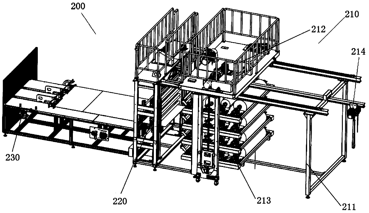
[0054] The fabric cutting and synthesis system includes such as figure 1 The cutting device 200 shown and as Figure 12 Fabric synthesis setup shown.

[0055] The cutting device 200 and the fabric synthesis device are separated, and can be set in different workshops or in the same workshop. In the embodiment, the cutting device 200 is set beside the fabric synthesis device in the same workshop.

[0056] like figure 1 As shown, the cutting device 200 includes a feeding part 210, a cutting part 220, a pulling part 230 and a cutting control part.

[0057] Feeding part 210, cutting part 220, pulling part 230 figure 1 set up in order from left to right.

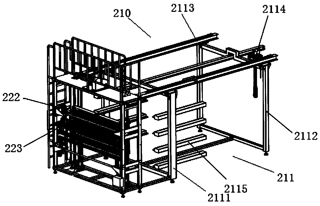
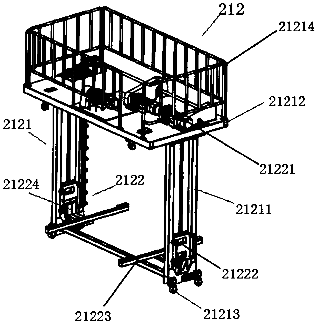
[0058] The feeding part 210 includes a feeding rack 211, a feeding mobile platform 212, a pallet unit 213, and an electric hoist 214.

[0059] like figure 2 As shown, the loading rack 211 includes a frame and a plurality of pallet hangers 2115 .

[0060] The frame includes a front frame 2111, a rear frame 2112, two platfo...


PUM


Abstract

The invention discloses a fabric cutting and synthesizing system. The system comprises a cutting device and a fabric synthesizing device; the cutting device comprises a feeding part, a cutting part and a pulling part which are arranged sequentially; the cutting part comprises a cutting frame, a front-end fabric clamping unit and a back-end fabric clamping and cutting unit; the front-end fabric clamping unit comprises a moving frame, a front-end upper clamping plate and a front-end lower clamping plate; the back-end fabric clamping and cutting unit comprises an upper action mechanism, a back-end upper clamping plate, a back-end lower clamping plate and a moving mechanism; the moving mechanism comprises a moving block moving on guiding rails; a cuter is arranged on the moving block; the fabric synthesizing device comprises a feeding part, a gluing part, a lower fabric feeding part, a water spraying part, a fabric synthesizing part and a fabric synthesizing receiving part which are arranged sequentially; the feeding part comprises a first weighing unit; and the first weighing unit is arranged at the lower part of a moving conveying belt mechanism and is used for weighing first fabricconveyed by a moving conveying belt.

Description

technical field [0001] The invention belongs to the field of automobile decoration, and relates to a fabric cutting and synthesis system, in particular to a fabric cutting and synthesis system for cutting and bonding various automobile decoration fabrics. Background technique [0002] The existing fabric cutting generally adopts the method of manual cutting, which can only cut one kind of fabric at a time, and cannot effectively smooth the fabric during cutting, and the fabric is wrinkled during cutting, which affects the cutting accuracy. Not only is the work efficiency low, but the labor cost is also increasing day by day. [0003] However, the existing fabric synthesis generally adopts the method of artificial synthesis. Artificial synthesis can only manually apply glue and spray water to the fabric each time. Due to the uneven operation of manual glue application, the range of water spray is limited, and the angle of water spray is not fixed. It is also difficult to ens...

Claims


Application Information

Patent Timeline
Patent Type & Authority Applications(China)
IPC IPC(8): D06H7/00D06B1/02D06B23/04B05C1/12B05C9/04B05C11/10B05C13/02B05B15/62B05B15/50B32B37/12B32B38/00
CPCD06H7/00D06B1/02D06B23/04B05C1/12B05C13/02B05C9/04B05C11/1005B05B15/62B05B15/50B32B37/1284B32B38/0004
Inventor 张玉强邓平吴凯计红根仲华
Owner CENMOY AUTOMATION TECH SHANGHAI CO LTD
Why Eureka
Try Eureka