Cutting device

A cutting device and tray technology, which is applied in the cutting of textile materials, textiles and papermaking, etc., can solve the problems of increased labor costs, low work efficiency, affecting cutting accuracy, etc., so as to reduce labor costs, improve work efficiency, and cut dimensional accuracy. high effect

Pending Publication Date: 2020-07-03
CENMOY AUTOMATION TECH SHANGHAI CO LTD
View PDF0 Cites 0 Cited by
  • Summary
  • Abstract
  • Description
  • Claims
  • Application Information

AI Technical Summary

Problems solved by technology

[0002] The existing fabric cutting generally adopts the method of manual cutting. Manual cutting can only cut one kind of fabric at a time, and the fabric cannot be effectively flattened during cutting, and the fabric is wrinkled during cutting, which affects the cutting accuracy.
Not only the work efficiency is low, but the labor cost is also increasing day by day
[0003] In addition, manual cutting is easy to move the fabric during cutting, which makes the dimensional accuracy of the fabric low. In addition, when cutting, it is easy to scratch yourself with a knife, which affects personal safety.

Method used


Image

  • Cutting device
  • Cutting device
  • Cutting device

Examples


Embodiment

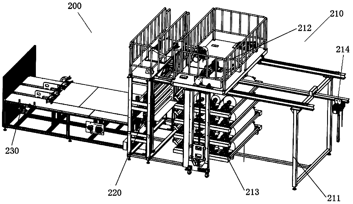
[0030] Such as figure 1 As shown, the cutting device 200 includes a feeding part 210 , a cutting part 220 , a pulling part 230 and a control part.

[0031] Feeding part 210, cutting part 220, pulling part 230 figure 1 set up in order from left to right.

[0032] The feeding part 210 includes a feeding rack 211 , a moving loading platform 212 , a tray unit 213 , and an electric hoist 214 .

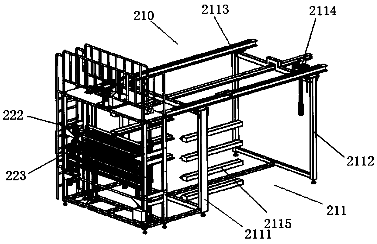
[0033] Such as figure 2 As shown, the loading rack 211 includes a frame and a plurality of pallet hangers 2115 .

[0034] The frame includes a front frame 2111, a rear frame 2112, two platform guide rails 2113, and an electric hoist guide rail 2114.

[0035] The front frame 2111 is a door-shaped frame and is vertically arranged on the ground.

[0036] The rear frame 2112 is a door-shaped frame, vertically arranged on the ground, opposite to and parallel to the front frame 2111 .

[0037] Two platform guide rails 2113 are arranged on the top of the front frame 2111 and the rear frame ...


PUM


Abstract

The invention discloses a cutting device. The cutting device comprises a feeding part, a cutting part and a traction part which are sequentially arranged, wherein the feeding part comprises a feedingframe, a feeding moving platform and a tray unit, the feeding moving platform is movably arranged on the feeding frame, the feeding moving platform comprises a tray lifting mechanism, the tray liftingmechanism comprises a lifting piece, the tray unit comprises a plurality of coiled material clamping assemblies with ejection heads, the cutting part comprises a cutting frame, a front-end fabric clamping unit and a rear-end fabric clamping and cutting unit, the front-end fabric clamping unit comprises a moving frame, a front-end upper clamping plate and a front-end lower clamping plate, the front-end upper clamping plate and the front-end lower clamping plate are used for clamping at least one kind of fabric, the rear-end fabric clamping and cutting unit comprises an upper action mechanism,a rear-end upper clamping plate, a rear-end lower clamping plate and a moving mechanism, the moving mechanism comprises a cutter arranged on a moving block, the traction part comprises a dragging mechanism, and a plurality of clamping claws used for grabbing the fabric are arranged on a dragging head of the dragging mechanism.

Description

technical field [0001] The invention belongs to the technical field of automobile decoration and relates to a cutting device, in particular to a cutting device for cutting fabrics. Background technique [0002] The existing fabric cutting generally adopts the method of manual cutting, which can only cut one kind of fabric at a time, and cannot effectively smooth the fabric during cutting, and the fabric is wrinkled during cutting, which affects the cutting accuracy. Not only is the work efficiency low, but the labor cost is also increasing day by day. [0003] In addition, manual cutting is easy to move the cloth during cutting, which makes the dimensional accuracy of the cloth low. In addition, when cutting, it is easy to scratch yourself with a knife, which affects personal safety. Contents of the invention [0004] In order to solve the above problems, one object of the present invention is to provide a cutting device. [0005] The invention provides a cutting device,...

Claims


Application Information

Patent Timeline
Patent Type & Authority Applications(China)
IPC IPC(8): D06H7/04
CPCD06H7/04
Inventor 张玉强吴凯计红根仲华
Owner CENMOY AUTOMATION TECH SHANGHAI CO LTD
Why Eureka
Try Eureka