Tooth surface quenching device for rack

A technology of quenching device and rack, applied in the direction of quenching device, heat treatment equipment, furnace, etc., can solve the problems of easy deformation of rack, difficult to observe, end upturning, etc., to ensure quality, improve effect, facilitate recycling and other problems. processing effect

Pending Publication Date: 2020-07-14
台州莱德齿条有限公司
View PDF1 Cites 3 Cited by
  • Summary
  • Abstract
  • Description
  • Claims
  • Application Information

AI Technical Summary

Problems solved by technology

In the existing quenching machine tool as mentioned above, during the quenching process of the rack, since the rack is a long strip structure, the rack is easily deformed after being heated during the quenching process, thus causing the end to be upturned. Therefore, it is easy to cause The quenching effect of the tooth surface of each part of the rack is inconsistent, and the whole rack will be slightly deformed and bent after quenching, which will affect the quality of the product
[0004] In order to ensure the quality of the product, the conventional method is: during the quenching process, an operator is required to hit the rack with a hammer or a hammer from time to time to repress the end of the rack that has been warped due to deformation. However, the rack is clamped on the fixture during the quenching process, so the deformation and upturning are difficult to observe with the naked eye. The strength and frequency of the knocking are all based on the experience of the staff, and it is difficult to ensure that each knocking is maintained. Consistent, but also need to invest a lot of labor costs

Method used


Image

  • Tooth surface quenching device for rack
  • Tooth surface quenching device for rack
  • Tooth surface quenching device for rack

Examples


Embodiment 1

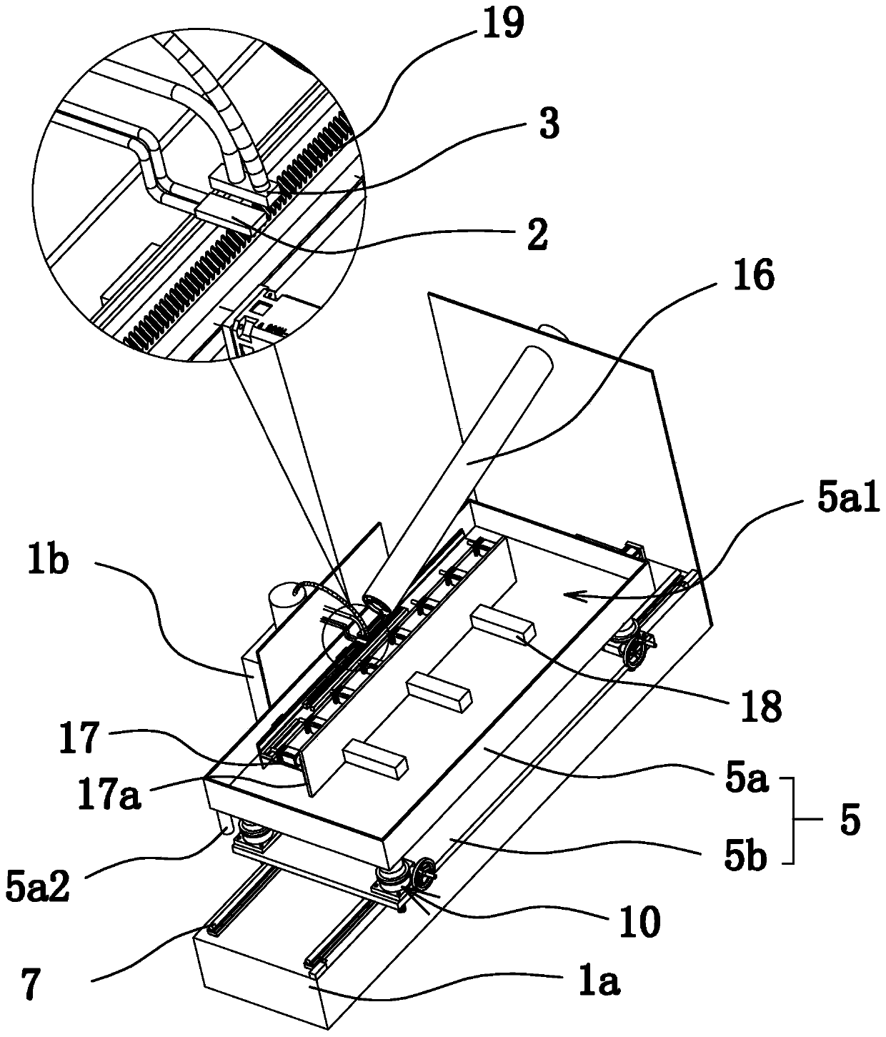
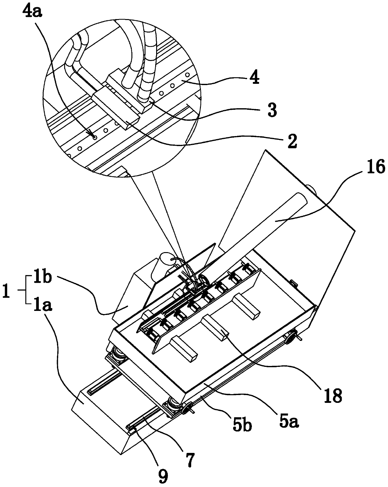
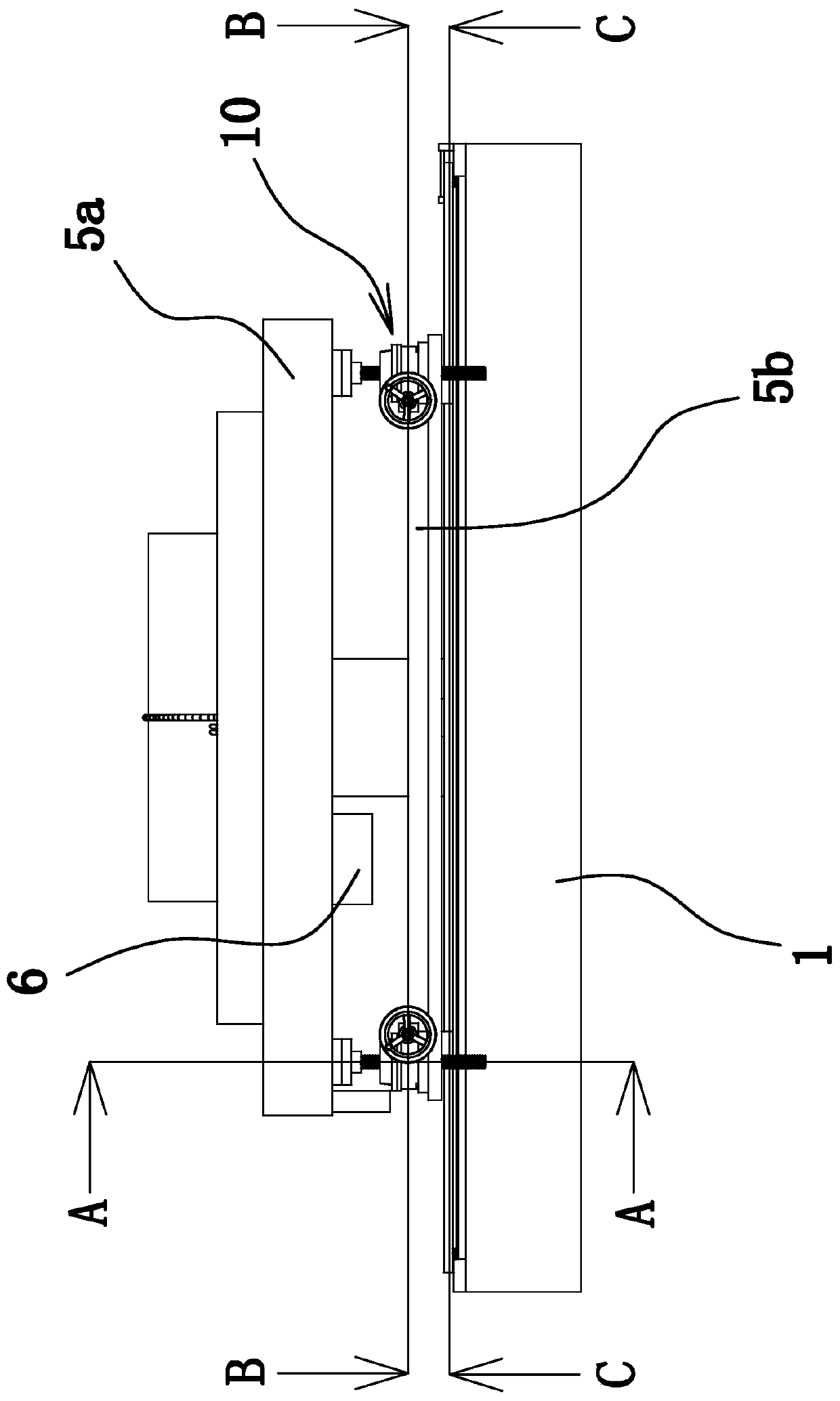
[0034] Such as Figure 1-6 As shown, the tooth surface quenching device of the rack includes a frame 1, a quenching head 2, a quenching liquid nozzle 3, a clamp 4 for clamping and positioning the rack 19, and a quenching plate 5 with a mounting cavity 5a1. Frame 1 includes frame body one 1a and frame body two 1b, frame body one 1a and frame body two 1b are arranged separately, frame body two 1b is provided with a liquid storage tank for storing quenching liquid, quenching head 2 and quenching liquid nozzle 3 are all fixed on the frame 1, and the quenching liquid nozzle 3 communicates with the liquid storage tank.

[0035] The quenching tray 5 includes a base plate 5b and a disc-shaped disc body 5a, and the disc body 5a is arranged on the base plate 5b. A slide rail 7 is fixed on the frame body 1a, and there are two slide rails 7. Sliders 8 are provided on the bottom of both sides of the base plate 5b, and the slide blocks 8 are slidably connected on the slide rails 7. The dr...

Embodiment 2

[0045] The structure of this embodiment is basically the same as that of Embodiment 1, the difference being that the adsorbent is an electromagnetic chuck, the electromagnetic chuck is elongated and arranged at the bottom of the fixture 4, and the magnetically conductive panel of the electromagnetic chuck is flush with the bottom surface of the fixture 4 flat. The rack 19 is clamped and positioned in the fixture 4, and is attached to the bottom surface of the fixture 4 and the magnetically conductive panel of the electromagnetic chuck. The electromagnetic chuck generates magnetic force through the internal coil energization, and the rack 19 is firmly sucked by the magnetically conductive panel. Make it always keep close to the bottom surface of the fixture 4, therefore, in the quenching process, even if the rack 19 is heated, it will not be deformed and upturned, which improves the quenching effect of the tooth surface and ensures the quality of the product.


PUM


Abstract

The invention provides a tooth surface quenching device for a rack, and belongs to the technical field of machines. The problem that an existing quenching device is poor in quenching effect is solved.The tooth surface quenching device for the rack comprises a machine frame, a quenching head, a quenching liquid nozzle, a quenching disc with a mounting cavity and a clamp used for clamping and positioning the rack, the quenching head and the quenching liquid nozzle are fixed to the machine frame, the quenching head and the quenching liquid nozzle are located above the clamp and are opposite to the clamp, the quenching disc is mounted on the machine frame and can slide back and forth in the horizontal direction relative to the machine frame, the clamp is mounted in the mounting cavity of thequenching disc, the bottom face of the clamp is a plane, the quenching disc is provided with a sucking part, the sucking part can suck the bottom of the rack to enable the rack to be tightly attachedto the bottom face of the clamp, the sucking part can generate sucking force to enable the bottom of the rack to be firmly sucked, in the quenching process, even if the rack is heated, deforming and upwarping cannot be generated, the tooth surface quenching effect is improved, and the product quality is ensured.

Description

technical field [0001] The invention belongs to the technical field of machinery and relates to a tooth surface quenching device of a rack. Background technique [0002] The rack is a special gear with teeth distributed on the bar body, which is mainly divided into straight toothed racks and helical toothed racks. During the processing of the rack, it is often necessary to quench the tooth surface of the rack to transform the surface structure into martensite, thereby improving the hardness, wear resistance and fatigue strength of the tooth surface, and prolonging its wear life. [0003] In the prior art, the quenching of the tooth surface of the rack is completed on a quenching machine tool. For example, a Chinese patent application (application number: 201310376016.8) discloses a workpiece quenching machine tool, including a bed body; a quenching system is arranged on the bed body; The body is equipped with a motion fixture system; the bed body is also equipped with a wat...

Claims


Application Information

Patent Timeline
Patent Type & Authority Applications(China)
IPC IPC(8): C21D1/06C21D1/667C21D9/00
CPCC21D1/06C21D1/667C21D9/0068
Inventor 张绍明
Owner 台州莱德齿条有限公司
Why Eureka
Try Eureka