
Fixing protection device for lithium battery

A technology for fixed protection and lithium batteries, which is applied to battery components, circuits, electrical components, etc., can solve the problems of single traditional fixed structure, inconvenient fixed operation, poor fixed protection effect of lithium batteries, etc., to facilitate promotion and promotion Test effect, practical effect

Inactive Publication Date: 2020-07-10
张 长成
View PDF0 Cites 1 Cited by
  • Summary
  • Abstract
  • Description
  • Claims
  • Application Information

AI Technical Summary

Problems solved by technology

[0003] When performing performance tests on lithium batteries, lithium battery fixed protection devices are needed, but the existing devices have a single traditional structure for fixing lithium batteries, the fixing operation is not convenient enough, and the effect of fixing and protecting lithium batteries is poor, so it needs to be improved

Method used


Image

  • Fixing protection device for lithium battery
  • Fixing protection device for lithium battery
  • Fixing protection device for lithium battery

Examples


Embodiment 1

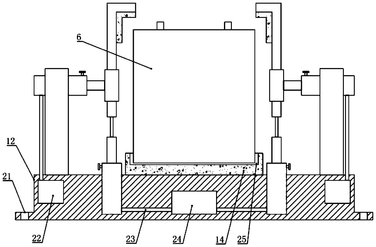
[0017] see figure 1 , in an embodiment of the present invention, a fixed protection device for a lithium battery includes a fixed frame 7 and a fixed base 12, and an elastic support pad 14 matching with the lithium battery 6 is installed in the middle of the top of the fixed base 12. The top outer side of the base 12 is installed and fixed with a plurality of fixed frames 7 distributed in the circumferential direction, and the fixed frame 7 is mounted with a horizontally telescopic fixed assembly 1, and one end of the laterally telescopic fixed assembly 1 near the elastic support pad 14 is installed with a support sleeve. 3. An L-shaped fixing plate 4 is co-operated and slidably arranged on the supporting sleeve 3. The upper part of the L-shaped fixing plate 4 is further equipped with an elastic protection pad 5 on the side away from the lateral telescopic fixing assembly 1. The L-shaped fixing plate 4 The lower end of the fixed plate 4 is connected with the vertically telesco...

Embodiment 2

[0020] see Figure 1-4 , the difference between this embodiment and embodiment 1 is:

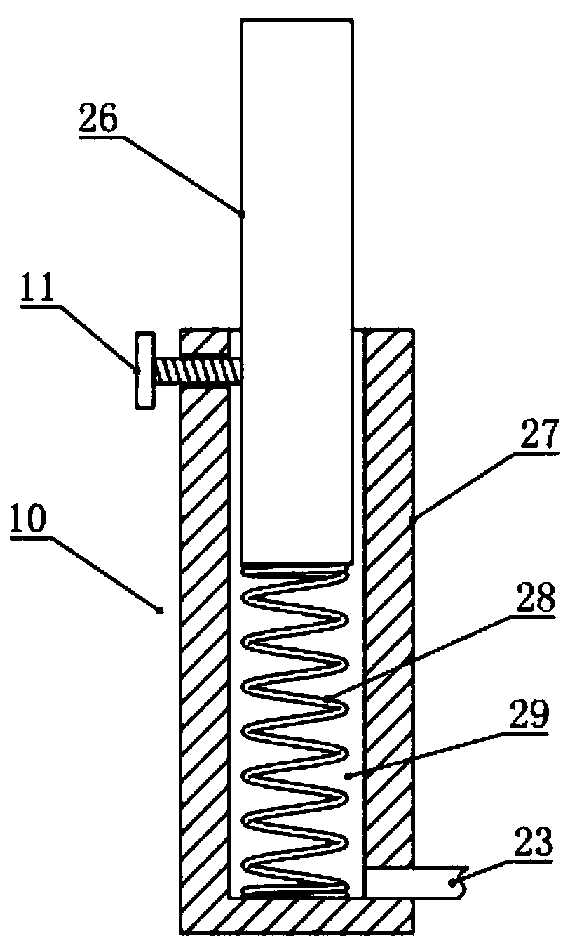
[0021] In this example, if figure 1 and 3 As shown, the structure of the horizontally telescopic fixing assembly 1 and the vertically telescopic fixing assembly 10 is the same, except that the horizontally telescopic fixing assembly 1 is arranged horizontally, and the vertically telescopic fixing assembly 10 is vertically arranged, and the horizontally telescopic fixing assembly 1 and The vertically telescopic fixing assembly 10 all includes a telescoping rod 26, a mounting cylinder 27, a spring 28 and a pneumatic chamber 29, and a pneumatic chamber 29 is provided in the mounting cylinder 27, and a telescopic rod 26 is arranged for sliding in the pneumatic chamber 29, and the pneumatic chamber Also be equipped with spring 28 in 29, one end of spring 28 is fixed on the end of telescopic rod 26, and the other end of spring 28 is fixed on the end of pneumatic chamber 29 far away from telescop...


PUM


Abstract

The invention relates to the technical field of lithium batteries, in particular to a fixing protection device for a lithium battery. The device comprises fixing frames and a fixing base, and the fixing frames are fixedly installed on the outer side of the top of the fixing base in the circumferential direction. A transverse telescopic fixing assembly is fixedly installed on each fixing frame, a supporting sleeve is fixedly installed at the end of the transverse telescopic fixing assembly, an L-shaped fixing plate is arranged on the supporting sleeve in a matched and sliding mode, and the lower end of the L-shaped fixing plate is connected with a vertical telescopic fixing assembly installed on the fixing base through an elastic strip. A pressurizer used for controlling the multiple transverse telescopic fixing assemblies to extend at the same time is further installed on the fixing base, and a negative pressure device used for controlling the multiple vertical telescopic fixing assemblies to shorten at the same time is further installed on the fixing base. The lithium battery fixing device is novel in structure, convenient to fix and operate and good in lithium battery fixing andprotecting effect.

Description

technical field [0001] The invention relates to the technical field of lithium batteries, in particular to a fixed protection device for lithium batteries. Background technique [0002] Lithium battery is a kind of battery that uses lithium metal or lithium alloy as the negative electrode material and uses non-aqueous electrolyte solution. Due to the very active chemical properties of lithium metal, the processing, storage and use of lithium metal have very high environmental requirements, but with With the development of science and technology, lithium batteries have become the mainstream now. [0003] When performing performance tests on lithium batteries, lithium battery fixing protection devices are required, but the existing devices have a single traditional structure for fixing lithium batteries, the fixing operation is not convenient enough, and the fixing protection effect on lithium batteries is poor, so it needs to be improved. Therefore, in view of the above curr...

Claims


Application Information

Patent Timeline
IPC IPC(8): H01M2/10
CPCH01M50/20Y02E60/10
Inventor 张长成
Owner 张 长成
Learn More