Oil-free screw structure and method for adjusting gap of synchronous rotors thereof

An adjustment method and rod structure technology, which is applied in the direction of elastic fluid rotary piston type/oscillating piston type pump combination, rotary piston type pump, rotary piston type machinery, etc., can solve the problem of increasing energy consumption and increasing blank cost , complex adjustment methods and other issues, to achieve the effect of high automation level and fast adjustment

Pending Publication Date: 2020-07-10
NINGBO BAOSI ENERGY EQUIP
View PDF0 Cites 5 Cited by
  • Summary
  • Abstract
  • Description
  • Claims
  • Application Information

AI Technical Summary

Problems solved by technology

[0003] However, the existing oil-free screw structure has the following technical problems: cooling oil is required to cool the synchronous gear 3a, and there will be more oil cooling systems in the design structure of the main engine, which increases the cost of the blank to a certain extent; in addition, the cooling oil has a certain The risk of entering the compression chamber and passing through the exhaust port will affect the working environment of the actual gas application; and the existence of the synchronous gear 3a increases energy consumption, which is not conducive to the performance of the unit; in addition, the synchronous gear 3a is used for synchronization When adjusting the rotor gap, the adjustment method is very complicated, and manual measurement of the gap with a feeler gauge is required, which takes a long time to adjust and there are manual measurement errors

Method used


Image

  • Oil-free screw structure and method for adjusting gap of synchronous rotors thereof
  • Oil-free screw structure and method for adjusting gap of synchronous rotors thereof
  • Oil-free screw structure and method for adjusting gap of synchronous rotors thereof

Examples


Embodiment 1

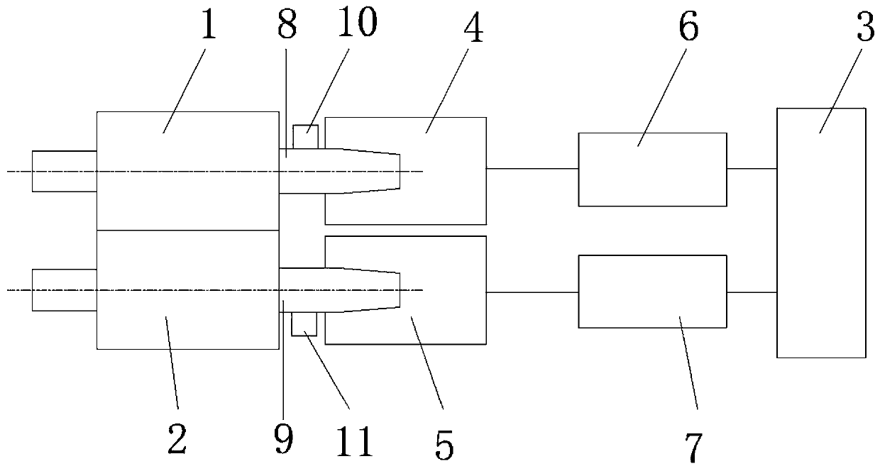
[0030] An oil-free screw structure, including a male rotor 1 and a female rotor 2, and also includes a controller 3, a first servo motor 4, a second servo motor 5, a first servo driver 6, a second servo driver 7, the first The servo motor 4 is connected to the first rotating shaft 8 of the male rotor 1, the second servo motor 5 is connected to the second rotating shaft 9 of the female rotor 2, and the first servo motor 4 and the second servo motor 5 are respectively provided with a second A position detection device 10 and a second position detection device 11, the first position detection device 10 and the first servo motor 4 are electrically connected to the first servo drive 6, the second position detection device 11 and the second servo motor 5 are all electrically connected with the second servo driver 7, and the first servo driver 6 and the second servo driver 7 are all connected in communication with the controller 3; the controller 3 can be a PLC controller 3, and the f...

Embodiment 2

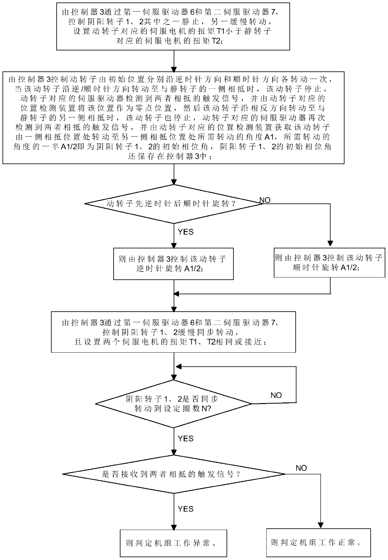
[0035] A method for adjusting the clearance of synchronous rotors with an oil-free screw structure, comprising the following steps:

[0036] (1) Through the first servo driver 6 and the second servo driver 7, the controller 3 controls one of the male and female rotors 1, 2 to be stationary and the other to rotate slowly, and the torque T1 of the servo motor corresponding to the moving rotor is set to be smaller than that corresponding to the stationary rotor The torque T2 of the servo motor, in this embodiment, the torque T2 of the servo motor corresponding to the fixed rotor is set to 70% to 100% of its rated value, and 100% of its rated value can be selected, and the torque T2 of the servo motor corresponding to the moving rotor is set. The torque T1 is 1% to 10% of its rated value, and 5% of its rated value can be selected. The speed V1 of the moving rotor slowly rotates is 1 circle / minute to 2 circles / minute, and 1 circle / minute can be selected;

[0037] (2) The controller...


PUM


Abstract

The invention provides an oil-free screw structure. The oil-free screw structure comprises a male rotor and a female rotor and is characterized by further comprising a controller, a first servo motor,a second servo motor, a first servo driver and a second servo driver, the first servo motor is connected with a first rotating shaft of the male rotor, and the second servo motor is connected with asecond rotating shaft of the female rotor; and the first servo motor and the second servo motor are provided with a first position detection device and a second position detection device respectively,the first position detection device and the first servo motor are both electrically connected with the first servo driver, the second position detection device and the second servo motor are both electrically connected with the second servo driver, and the first servo driver and the second servo driver are both in communication connection with the controller. According to the oil-free screw structure, a synchronous gear is omitted, and a gap of the synchronous rotors can be automatically and rapidly adjusted. In addition, the invention further provides a method for adjusting the gap of the synchronous rotors of the oil-free screw structure.

Description

technical field [0001] The invention relates to the technical field of screw compressors, in particular to an oil-free screw structure and a method for adjusting the gap between synchronous rotors. Background technique [0002] like figure 1 As shown, the oil-free screw structure generally includes a male rotor 1a, a female rotor 2a, and a motor 4a for driving one of the rotors, the rotating shaft of the motor 4a is connected with the rotating shaft of the rotor through a coupling 5a, and the traditional The oil screw structure realizes the synchronous operation of the male and female rotors 1a, 2a through the synchronous gear 3a, and makes a certain gap between the tooth surfaces of the male and female rotors 1a, 2a. [0003] However, the existing oil-free screw structure has the following technical problems: cooling oil is required to cool the synchronous gear 3a, and there will be more oil cooling systems in the design structure of the main engine, which increases the co...

Claims


Application Information

Patent Timeline
IPC IPC(8): F04C18/16F04C23/02F04C28/00F04C28/08F04C28/06F04C28/04
CPCF04C18/16F04C23/02F04C28/00F04C28/08F04C28/06F04C28/04
Inventor 顾礼照王立光邬剑波蒋豪
Owner NINGBO BAOSI ENERGY EQUIP
Why Eureka
Try Eureka