
Artificial wave making device and artificial wave making method

A wave-making and artificial technology, applied in the field of artificial wave-making devices, can solve the problems of large occupied space, large dedicated space, multiple equipment, etc., and achieve the effect of easy installation and operation, less space occupied, and fewer parts.

Inactive Publication Date: 2020-07-10
何厚煌
View PDF6 Cites 0 Cited by
  • Summary
  • Abstract
  • Description
  • Claims
  • Application Information

AI Technical Summary

Problems solved by technology

For example, the utility model patent with the application number CN2016206418839 discloses vacuum wave-making equipment, which uses a vacuum pump to suck a certain amount of water to a certain height, then suddenly opens the valve and releases it into the wave-making pool, and the impact forms waves. This device is equipped with a vacuum unit , vacuum chamber, water inlet channel air chamber, and air pressure conversion chamber require a large number of equipment and a large dedicated space, requiring professional operators, and are not suitable for installation and use in small-scale pools such as family or hotel pools.
Also, the invention patent with the application number CN2019108362963 discloses a detachable floating platform artificial wave-making device, which includes a multi-section floating rectangular box body, and the multi-section box bodies are connected end to end to form a long floating platform. The space is fixed with connectors, and the rails mounted on the box are connected to each other in a straight line, and the wave generator reciprocates along the rails to create waves in the pool. This device also has many and complicated equipment, takes up a lot of space, and is difficult to maintain.

Method used


Image

  • Artificial wave making device and artificial wave making method
  • Artificial wave making device and artificial wave making method
  • Artificial wave making device and artificial wave making method

Examples


Embodiment Construction

[0022] The present invention will be described in more detail below in conjunction with the accompanying drawings and embodiments. The following descriptions are just examples for the convenience of understanding the present invention, and are not intended to limit the scope of the present invention.

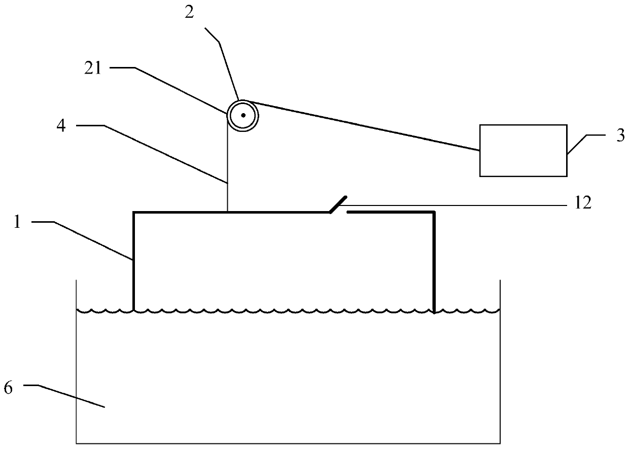
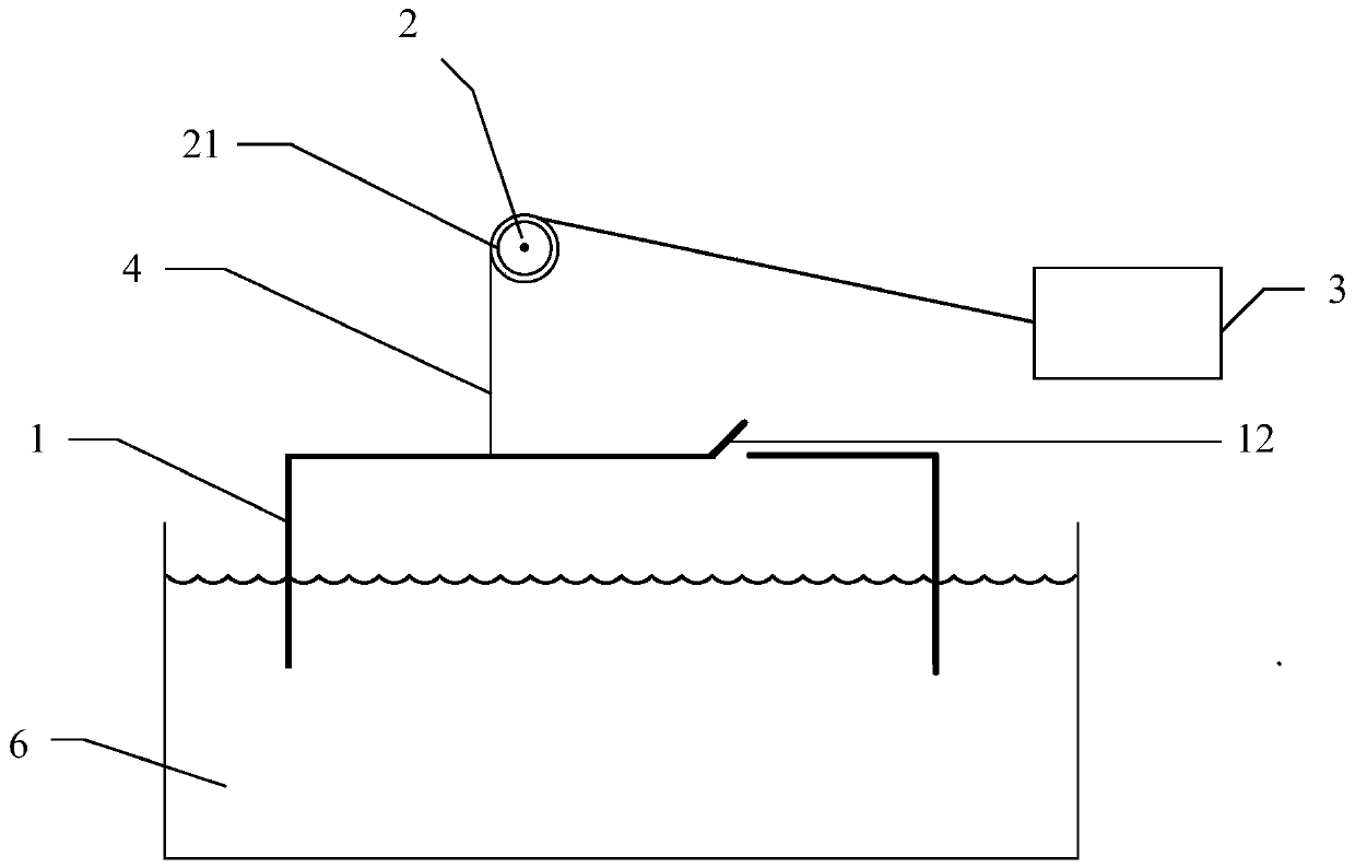
[0023] figure 1 It is a schematic structural view showing an artificial wave-making device according to an embodiment of the present invention. Such as figure 1 As shown, the artificial wave-making device of this embodiment has: a box body 1 , a supporting member 2 , a traction member 3 , and a connecting member 4 .

[0024] The box body 1 is a hollow structure with an opening 11 and a shutter 12 . The shape of the box can be cube, cuboid or sphere. Described box body 1 can adopt the material that can bear certain pressure to prepare, in case box body 1 is immersed in water body, or is subjected to the active force from water body when being pulled out from water body and th...


PUM


Abstract

The invention discloses an artificial wave making device and an artificial wave making method. The artificial wave making device comprises a box body (1), a supporting piece (2), a traction part (3) and a connecting piece (4); the box body (1) is a hollow structure provided with an opening (11) and a valve (12); the supporting piece (2) is arranged on the outer side of the box body (1); the traction part (3) is used for providing power; one end of the connecting piece (4) is connected to the box body (1), and the other end of the connecting piece (4) is connected to the traction part (3); andthe connecting piece (4) connects the box body (1) and the traction part (3) through the supporting piece (2), and the traction part (3) applies force to the connecting piece (4) to control the movement of the box body (1). The artificial wave making device requires few parts and little occupied space, is easy to mount and operate, does not need adjustment by professional personnel, and can be suitable for artificial wave making in small water pools at homes, hotels and the like.

Description

technical field [0001] The invention relates to an artificial wave-making device and an artificial wave-making method using the artificial wave-making device. Background technique [0002] Most water casinos increase the fun of water leisure by simulating river and sea waves in the wave pool. For example, the utility model patent with the application number CN2016206418839 discloses vacuum wave-making equipment, which uses a vacuum pump to suck a certain amount of water to a certain height, then suddenly opens the valve and releases it into the wave-making pool, and the impact forms waves. This device is equipped with a vacuum unit , vacuum chamber, water inlet channel air chamber, and air pressure conversion chamber require a large number of equipment and a large dedicated space, requiring professional operators, and are not suitable for installation and use in small-scale pools such as family or hotel pools. Also, the invention patent with the application number CN2019108...

Claims


Application Information

Patent Timeline
Patent Type & Authority Applications(China)
IPC IPC(8): E04H4/00
CPCE04H4/0006
Inventor 何厚煌
Owner 何厚煌
Learn More