
Steel beam and composite beam connecting structure

A technology for connecting structures and composite beams, applied in bridges, bridge forms, buildings, etc., can solve the problems of high prefabrication precision requirements, complicated connection methods and cumbersome processes, and achieve simple structure, smooth force transmission, and strong bearing capacity. Effect

Pending Publication Date: 2020-07-10
ANHUI TRANSPORTATION HLDG GRP CO LTD
View PDF3 Cites 3 Cited by
  • Summary
  • Abstract
  • Description
  • Claims
  • Application Information

AI Technical Summary

Problems solved by technology

[0006] As mentioned above, there are many forms of steel-concrete composite beams involved in the prior art, but the existing connection methods are complex and cumbersome, and require high prefabrication precision

Method used


Image

  • Steel beam and composite beam connecting structure
  • Steel beam and composite beam connecting structure
  • Steel beam and composite beam connecting structure

Examples


Embodiment

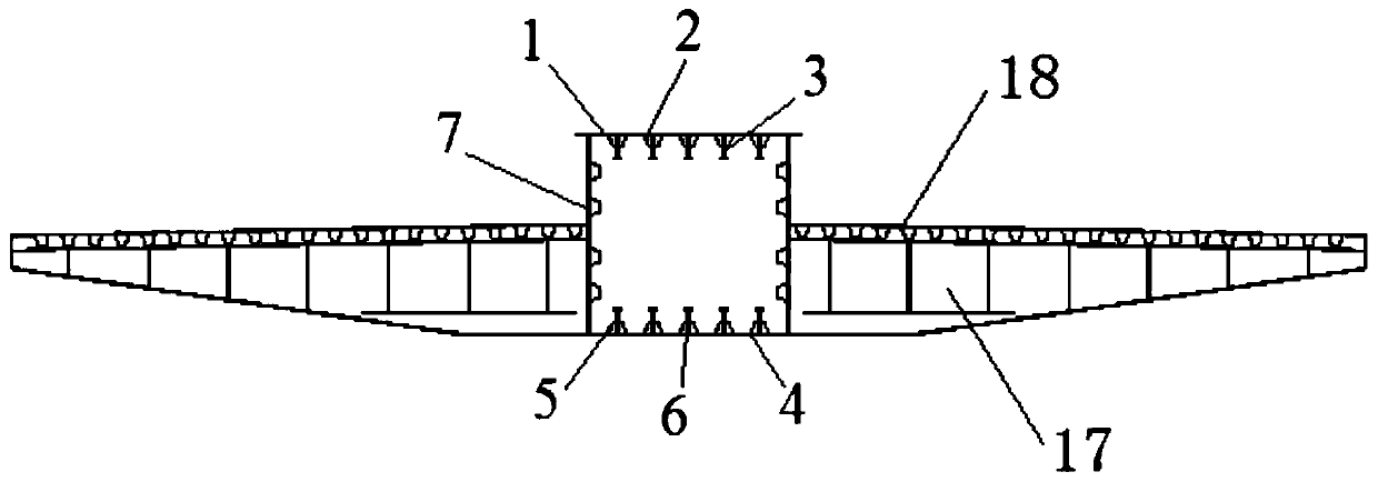
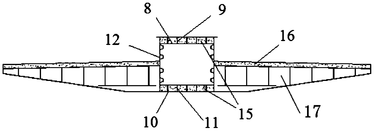
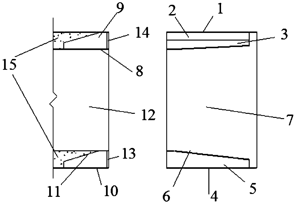
[0039] refer to figure 1 , figure 2 , image 3 , the present embodiment provides a connection structure of a steel beam and a composite beam, including a connected steel box girder and a composite beam.

[0040] In this embodiment, the steel box girder includes a central steel box girder main longitudinal beam and steel box girder cantilever plates connected to both sides of the steel box girder main longitudinal beam, and the steel box girder main longitudinal beam includes a steel beam top plate 1, a steel beam bottom plate 4 and The steel beam web 7 , the steel beam top plate 1 and the steel beam bottom plate 4 are respectively connected to the upper and lower ends of the steel beam web 7 , and the steel box girder cantilever plate is connected to the steel beam web 7 .

[0041]In this embodiment, the composite beam includes a composite beam main longitudinal beam in the center and composite beam cantilever plates connected on both sides of the composite beam main longit...


PUM


Abstract

The invention relates to a steel beam and composite beam connecting structure. The connecting structure comprises a steel box girder and a composite girder which are connected. The steel box girder comprises a steel box girder main longitudinal beam and steel box girder cantilever slabs connected to the two sides of the steel box girder main longitudinal beam. The steel box girder main longitudinal beam comprises a steel girder top plate, a steel girder bottom plate and a steel girder web. The steel beam top plate and the steel beam bottom plate are connected to upper and lower ends of the steel beam web. The composite girder comprises a composite girder main longitudinal beam and composite girder cantilever slabs connected to the two sides of the composite girder main longitudinal beam. The composite girder main longitudinal beam comprises a composite beam steel top plate, a composite girder steel bottom plate and a composite girder steel web. The composite girder steel top plate andthe composite girder steel bottom plate are respectively connected to the upper end and the lower end of the composite girder steel web, the steel beam web is welded with the composite beam steel web,the composite beam concrete is filled above the composite girder steel top plate, and the composite beam concrete is filled on the composite girder steel bottom plate. The connecting structure has the advantages of being simple in form, smooth in force transmission, convenient to connect and beneficial to standardized manufacturing and modular assembly of the hybrid beam of the cable-stayed bridge.

Description

technical field [0001] The invention belongs to the technical field of bridges, in particular to a connection structure of steel beams and composite beams. Background technique [0002] Steel girder bridges are the common structure of cable-stayed bridges. The steel has high rigidity and light weight, but the cost is high. Therefore, the use of steel-concrete composite girders can maximize the advantages of two different materials. [0003] Chinese patent CN110863417A discloses a steel-concrete composite girder bridge with rapid installation and its construction method. Between the bridge decks, through steel bars are penetrated into the circular lapped steel bars, the vertical and horizontal wet joints are poured with high-performance concrete, and the bottom plates of the longitudinally adjacent steel girders are connected by spliced ​​steel plates and high-strength bolts. The construction method mainly includes: prefabricated steel-concrete composite beams, hoisting in p...

Claims


Application Information

Patent Timeline
Patent Type & Authority Applications(China)
IPC IPC(8): E01D11/04E01D2/00E01D2/04
CPCE01D2/00E01D2/04E01D11/04
Inventor 胡可郑建中杨晓光曹光伦朱玉王胜斌孙海鹏邵虎石雪飞刘志权李夫凯陈亮唐国喜曹皓韩磊
Owner ANHUI TRANSPORTATION HLDG GRP CO LTD
Learn More