


Quick Research
Generate reliable direction feasibility study reports for your R&D in just a few steps.

Technical Q&A
Discover and master advanced knowledge NOW. Basics, ideas, possibilities, all at once.

Find Solutions
As an expert in R&D theories, this can generate solutions to your technical problems instantly.

Evaluate Feasibility
Analyze your overall solution with one click, know your potential R&D risks in advance.

Monitor Landscape
Get weekly tech updates, stay abreast of the latest tech innovations and key insights.
Existing cutting broadening roadbed structure in karst area and design and construction methods theref
A technology for karst areas and roadbeds, applied in the field of geotechnical engineering, can solve the problems of increased investment, high engineering risks, and high engineering costs, and achieve the effects of saving investment, controlling engineering investment, and simplifying construction.
- Summary
- Abstract
- Description
- Claims
- Application Information
AI Technical Summary
Problems solved by technology
Method used
Image

Examples
Embodiment 1
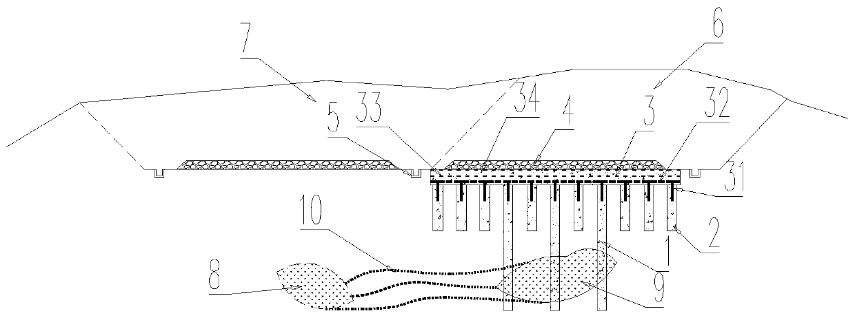
[0048] refer to figure 1 , the existing road cutting in the karst area of the present invention widens the subgrade structure, widens the subgrade 6 base karst cave 9 areas and arranges the long pile 1 and the short pile 2, widens the subgrade 6 base non-karst cave area and arranges the short pile 2; the light replacement body 3 is arranged on the long pile 1 and short pile 2 on top of the pile; soil filler 4 is filled on the light replacement body 3; drainage ditches 5 are arranged on both sides of the light replacement body 3.
[0049] In the above scenario:
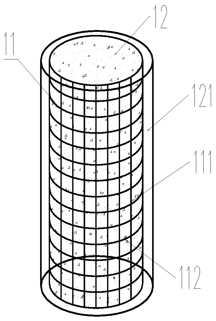
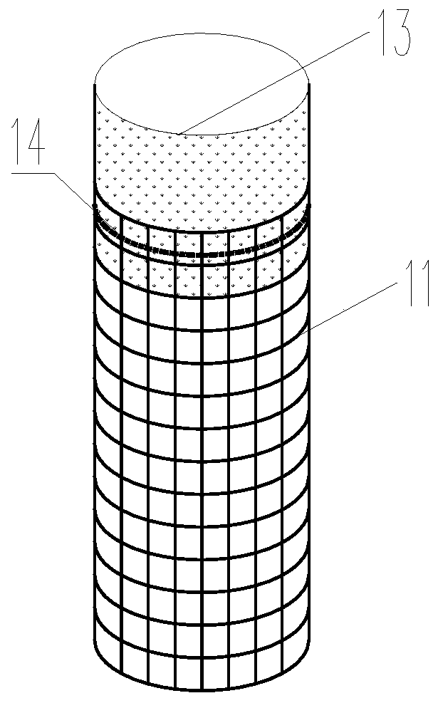
[0050] refer to figure 2 , 3 , both the long pile 1 and the short pile 2 are composite lightweight piles composed of a pile-forming lightweight body 12 and a composite reinforced cage 11 embedded in it, and the composite reinforced cage 11 is composed of vertical geogrids arranged at circumferential intervals The grid 111 and the annular geogrid 112 arranged at vertical intervals are composed of the vertical geog...
Embodiment 2
[0075] Such as Figure 1-3 As shown, this embodiment specifically demonstrates the design method for widening the subgrade 6 structure during construction, and the specific design process:
[0076] The design speed of a high-speed railway is 300km / h (ballastless track), and the line spacing is 4.8m. In order to meet the design requirements of introducing a large hub, it is necessary to widen the existing ballastless railway cutting and build a new cutting. The site belongs to the karst landform. The underlying complex karst. According to the geophysical prospecting data, it is determined that there is a hidden karst 8 at the base of the existing cutting 7, and there is an underlying karst cave 9 at the base of the newly built cutting. 9 The overlying stratum is strongly weathered limestone interbedded with sand and gravel. In order to reduce the disturbing influence of the newly-built cutting on the existing railway and control the project investment, the existing cutting 7 ...
PUM
| Property | Measurement | Unit |
|---|---|---|
| Thickness | aaaaa | aaaaa |
| Severe | aaaaa | aaaaa |
| Severe | aaaaa | aaaaa |
Abstract
Description
Claims
Application Information
 - R&D Engineer
- R&D Manager
- IP Professional
- Industry Leading Data Capabilities
- Powerful AI technology
- Patent DNA Extraction
Browse by: Latest US Patents, China's latest patents, Technical Efficacy Thesaurus, Application Domain, Technology Topic, Popular Technical Reports.
© 2024 PatSnap. All rights reserved.Legal|Privacy policy|Modern Slavery Act Transparency Statement|Sitemap|About US| Contact US: help@patsnap.com