Positioning device for tempered glass production stamping

A technology for stamping and tempering glass, which is applied in the pressing of glass, forming of glass, and re-forming of glass. Effect

Pending Publication Date: 2020-07-10
江苏久茂精密电子科技有限公司
View PDF0 Cites 1 Cited by
  • Summary
  • Abstract
  • Description
  • Claims
  • Application Information

AI Technical Summary

Problems solved by technology

[0004] For this reason, the embodiment of the present invention provides a positioning device for stamping processing of tempered glass production. By setting the positioning mechanism, when placing the glass, only need to place the glass inside the four positioning seats, and then start the motor to make the four positioning The seats are close to each other at the same time, and finally the glass is clamped and fixed to the center position on the base. At the same time, when the positioning seat moves, it will also drive the pressure plate down synchronously, so that the glass will be tightly attached to the base, effectively avoiding the corners of the glass. At the same time, by setting the buffer component, it can also effectively ensure that the glass will not be damaged due to excessive extrusion pressure when it is clamped, so as to solve the problem of placing the glass on the mold before the glass is stamped and formed in the prior art. On the other hand, when placing the glass, it is often necessary for the staff to repeatedly confirm whether the glass is placed in the correct position, and the staff is required to ensure that the glass is placed in place, and the corners cannot be tilted, which will affect the quality of subsequent stamping, resulting in low work efficiency.

Method used


Image

  • Positioning device for tempered glass production stamping
  • Positioning device for tempered glass production stamping
  • Positioning device for tempered glass production stamping

Examples


Embodiment 1

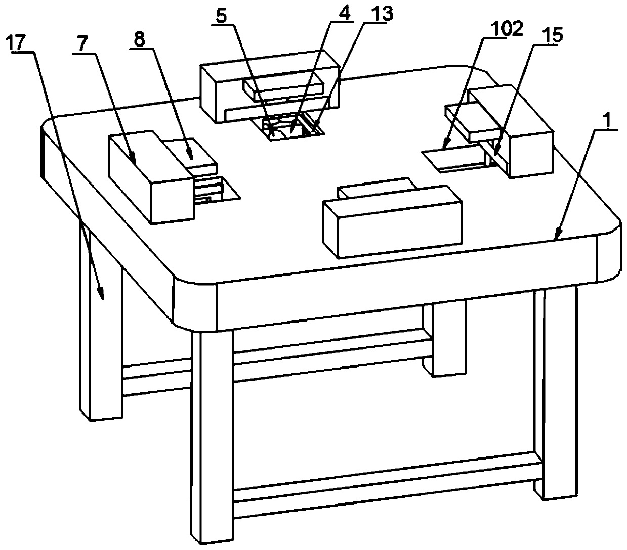
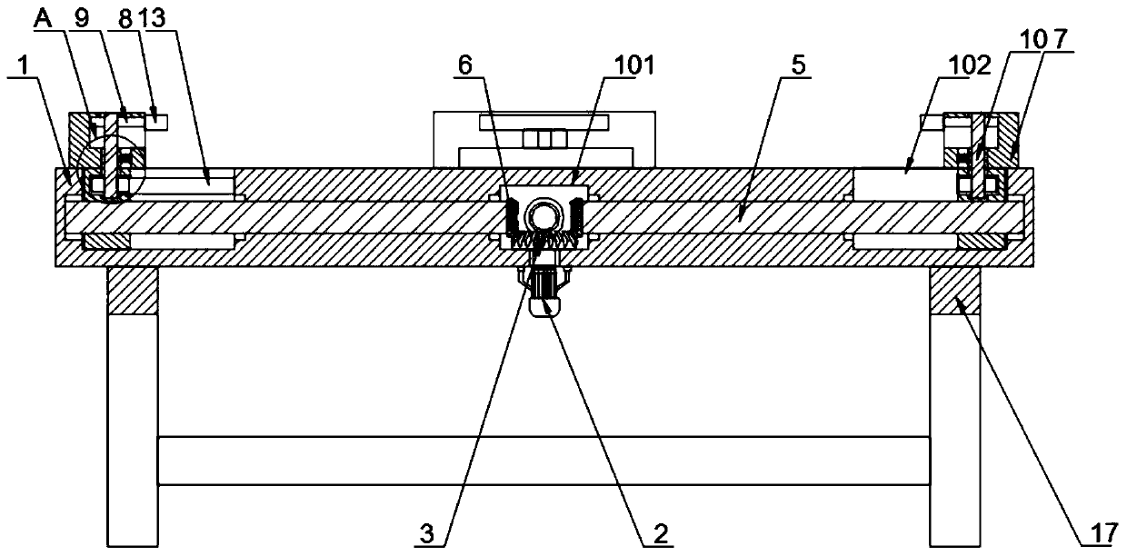
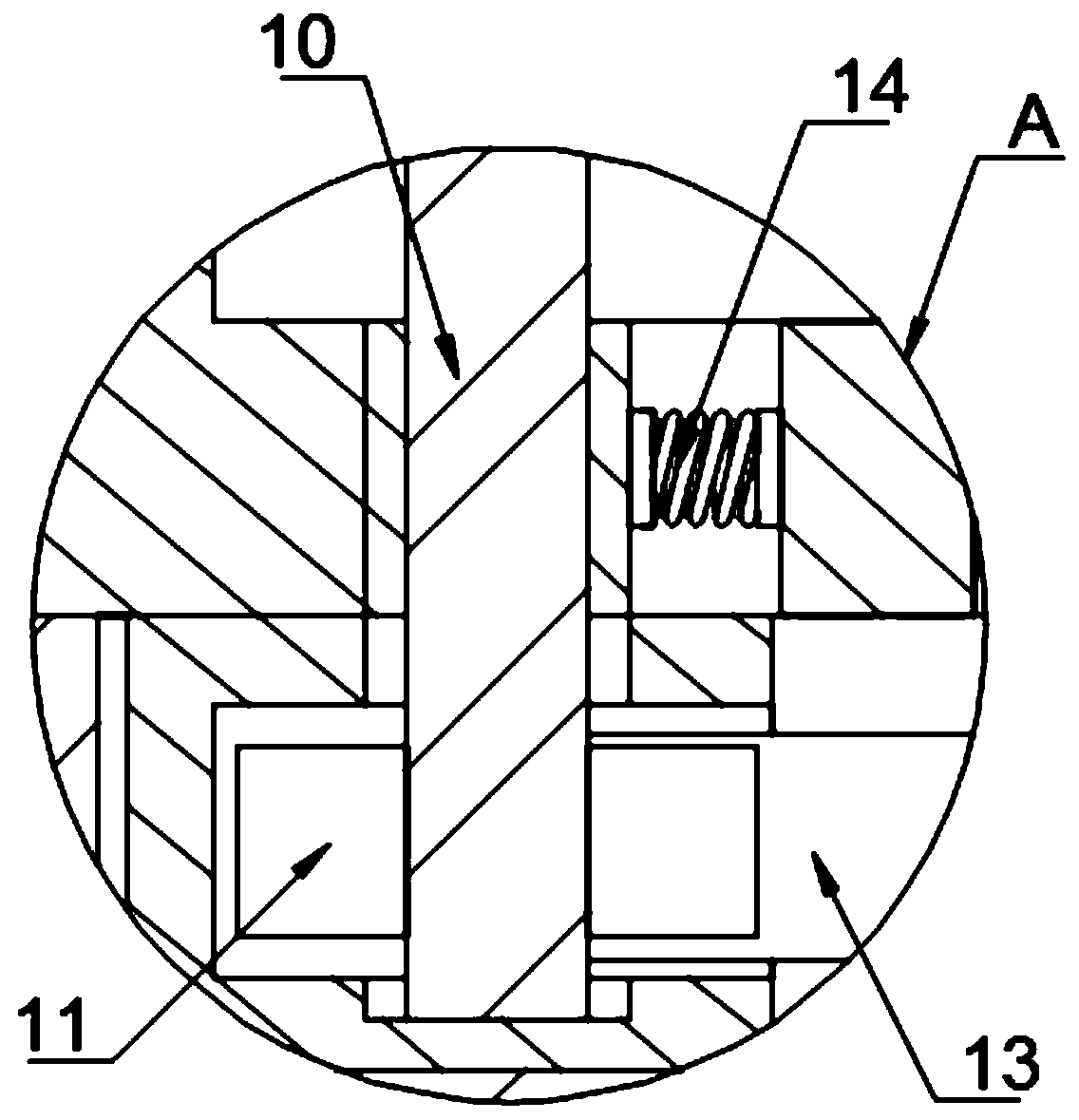
[0028] Refer to the attached figure 1 , figure 2 , image 3 and Image 6 , a positioning device for stamping processing of tempered glass production in this embodiment, comprising a base 1, a positioning mechanism is provided on the top of the base 1, and the bottom end of the positioning mechanism extends to the inside of the base 1;

[0029] The positioning mechanism includes a motor 2, the motor 2 is fixedly connected to the bottom of the base 1, a cavity 101 is provided inside the base 1, the top of the output shaft of the motor 2 extends to the inside of the cavity 101, and the output shaft of the motor 2 The first bevel gear 3 is fixedly connected, and the top of the base 1 is provided with four positioning components, and the four positioning components all include rectangular grooves 102, and the four rectangular grooves 102 are all opened on the top surface of the base 1, and the four positioning components The rectangular slots 102 are uniformly distributed outsi...

Embodiment 2

[0039] Refer to the attached figure 1 , Figure 4 , Figure 5 and Image 6 The difference from Example 1 is that the buffer assembly includes an air bag ring 18 and a rubber plate 19, and the four rubber plates 19 are respectively embedded in the inner surfaces of the four positioning seats 7, and the air bag ring 18 is located on the rubber plate 19 and the inner side of the positioning seat 7, the two sides of the air bag ring 18 are respectively fixedly connected with the rubber plate 19 and the positioning seat 7.

[0040] The specific implementation scenario is: when the four positioning seats 7 are close to the placed glass at the same time, and when the glass is clamped and fastened, the rubber plate 19 will squeeze the airbag ring 18 when the extrusion pressure is too large, so that the airbag ring 18 shrinks and deforms against the pressure. Cushion absorption is carried out, so as to avoid damage to the glass due to excessive extrusion pressure when it is fixed. ...


PUM


Abstract

The invention discloses a positioning device for tempered glass production stamping, and particularly relates to the technical field of glass production stamping. The positioning device comprises a base, a positioning mechanism is arranged at the top of the base, and the bottom end of the positioning mechanism extends into the base; the positioning mechanism comprises a motor, the motor is fixedlyconnected to the bottom of the base, a cavity is formed in the base, the top end of an output shaft of the motor extends into the cavity, and the output shaft of the motor is fixedly connected to a first bevel gear. By setting the positioning mechanism glass only needs to be placed on the inner sides of four positioning seats, the motor is started to enable the four positioning seats to get closeto each other at the same time, finally, the glass is clamped and fixed to the center of the base, and meanwhile, when the positioning seats move, pressing plates are synchronously driven to press downwards, so that the glass is tightly attached to the base, and the situations that corners of the glass tilt and the like are effectively avoided.

Description

technical field [0001] The invention relates to the technical field of glass production and processing, in particular to a positioning device for stamping and processing of tempered glass production. Background technique [0002] Stamping is a forming processing method that applies external force to plates, strips, pipes and profiles by presses and molds to cause plastic deformation or separation to obtain workpieces (stamping parts) of required shape and size. Stamping and forging belong to plastic processing (or pressure processing) and are collectively called forging. The blanks for stamping are mainly hot-rolled and cold-rolled steel sheets and strips. Among the steel products in the world, 60-70% are plates, most of which are stamped into finished products. When glass is produced, it often needs to be stamped to achieve the corresponding shape or size. However, when glass is stamped, it often requires work. The personnel repeatedly confirmed whether the placement of t...

Claims


Application Information

Patent Timeline
Patent Type & Authority Applications(China)
IPC IPC(8): C03B11/00C03B23/02
CPCC03B11/00C03B23/02
Inventor 窦进军
Owner 江苏久茂精密电子科技有限公司
Why Eureka
Try Eureka