
A pulsed gas jet generator with adjustable excitation frequency and duty cycle

A technology of pulsed gas and excitation frequency, applied in the direction of injection device, injection device, etc., can solve the problems of small flow rate, high cost and risk, unable to meet research or application needs, etc., and achieve the effect of precise adjustment of rotation speed.

Active Publication Date: 2021-01-01
HEFEI UNIV OF TECH
View PDF7 Cites 0 Cited by
  • Summary
  • Abstract
  • Description
  • Claims
  • Application Information

AI Technical Summary

Problems solved by technology

External excitation mostly uses plasma discharge or cavity oscillation to generate pulsed jets, among which high-voltage equipment (above 10kV) is required for plasma discharge, which is costly and has certain risks; pulsed jets generated by cavity oscillations are mainly used in The difference between the working pressure and the ambient pressure is not large (within 0.1MPa), and the flow velocity (10m / s or less) is small, which cannot meet the research or application requirements of higher pressure and larger flow

Method used


Image

  • A pulsed gas jet generator with adjustable excitation frequency and duty cycle
  • A pulsed gas jet generator with adjustable excitation frequency and duty cycle
  • A pulsed gas jet generator with adjustable excitation frequency and duty cycle

Examples


Embodiment 1

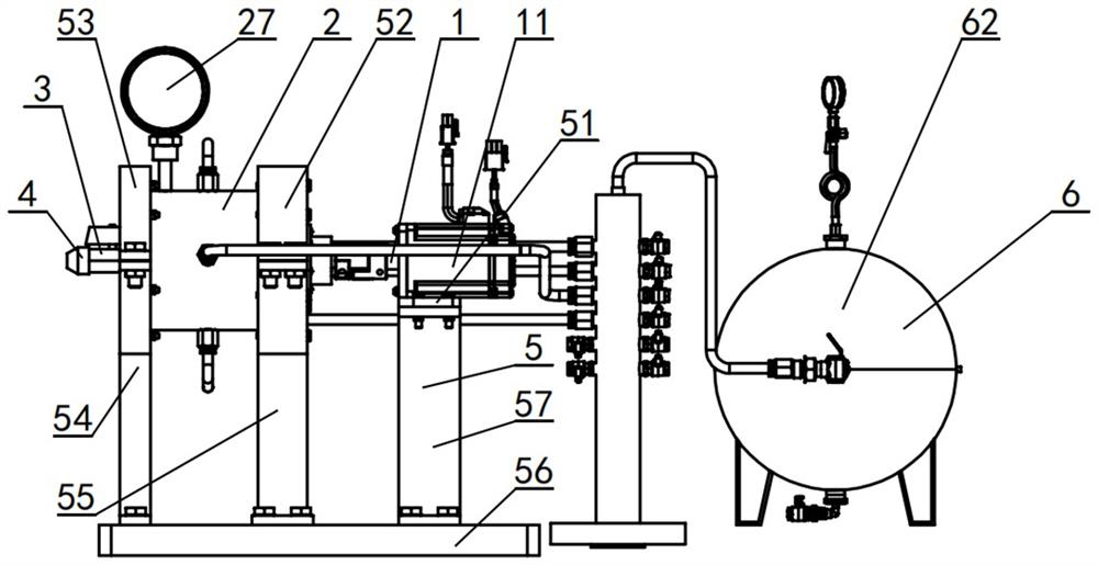
[0041]Seefigure 1 A pulse gas jet generator with adjustable excitation frequency and duty ratio mainly includes a rotating mechanism 1, a generating cavity mechanism 2 and an air supply mechanism 6.

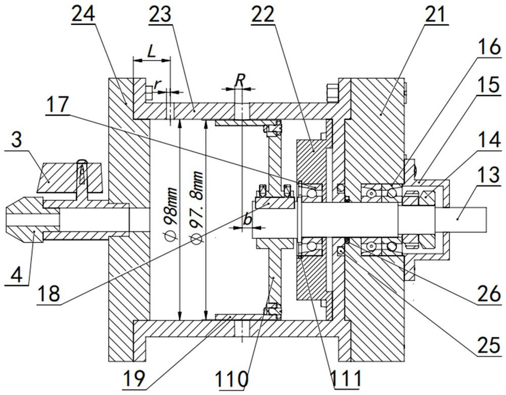
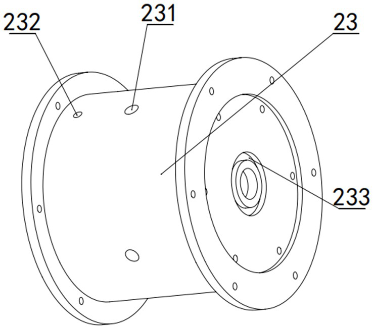
[0042]Seefigure 1 withfigure 2 , The rotating mechanism 1 includes a motor 11, a rotating shaft 13, and a rotating disk 110. Motor 11 is a Panasonic MHMF042L1U2M servo motor with a rated power of 400W, a rated speed of 3000r / min, and a rated torque of 1.27N·m. The rotating disk 110 is fixedly installed on one end of the rotating shaft 13 through a flat key 18 and a set screw, and the other end of the rotating shaft 13 is fixedly connected to the output shaft of the motor 11 through a coupling 12. The middle part of the rotating shaft 13 is fixed on the first flange 21 by a pair of first bearings 16 which are angular contact ball bearings. Four blades 19 are uniformly installed on the circumference of the rotating disk 110. The four blades 19 are parallel to the rotating shaft 13 and the a...

Embodiment 2

[0051]Example 2 The pulse jet has a duty ratio of 0.5, a frequency of 40 Hz, and a working pressure of 0.2 MPa. SeePicture 9 Under this working condition, a blade 19 with a central angle θ of 45°, a width c of 37.43mm, and a pulse jet duty ratio D=θ / 90°=0.5 are used. Under this working condition, the motor speed n is 600r / min, corresponding to the frequency f=4n / 60=40Hz. Before the device works, close the first ball valve 3 and the second ball valve 61; when it starts to work, adjust the working pressure of the pressure reducing valve 63 to 0.2MPa, set the motor speed to 600r / min, open the second ball valve 61, and pressure the gas tank 62. Continuously fill the cylinder body 23 with high-pressure gas through the four air inlets 231. When the value of the first pressure gauge 27 shows 0.2MPa, open the first ball valve 3, and after the air flow is stable, start the motor 11, repeat Example 1 Operation.

Embodiment 3

[0053]Example 3 The pulse jet has a duty ratio of 2 / 3, a frequency of 20 Hz, and a working pressure of 0.5 MPa. Before the device works, replace the blade 19, seePicture 10, The central angle θ of each blade 19 is 60°, and the width c is 48.9 mm. According to the calculation formula of the duty cycle D=θ / 90°=2 / 3. Under this working condition, the motor 11 rotates speed n to 300r / min, corresponding to the pulse frequency f=4n / 60=20Hz. After installation, close the first ball valve 3 and the second ball valve 61; when starting to work, adjust the pressure reducing valve 63 to a working pressure of 0.5MPa, set the motor speed to 600r / min, open the second ball valve 61, and the pressure tank 62 passes The four air inlets 231 are continuously filled with high-pressure gas into the cylinder body 23. When the value of the first pressure gauge 27 shows 0.5 MPa, the first ball valve 3 is opened. After the air flow is stable, the motor 11 is started, and the example 1 is repeated. operating.


PUM


Abstract

The invention relates to a pulse gas jet generation device capable of adjusting the excitation frequency and the duty ratio, and belongs to the technical field of gas jet. The device comprises a rotating mechanism, a generation cavity mechanism and a gas supply mechanism. The rotating mechanism comprises a motor and a rotating disc, and four blades are evenly distributed on the circumference of the rotating disc. The generation cavity mechanism comprises a cylinder body, and four gas inlets are evenly distributed on the same circumference of the cylinder body. The rotating disc is located in the cylinder body. The gas supply mechanism comprises a pressure gas storage tank. During work, high-pressure gas flow enters the cylinder body through the gas inlets, when the blades do not block thegas inlets, high-pressure gas is sprayed out from a nozzle while being input from the gas inlets, and the work pressure intensity in the cylinder body does not change; in the process that the blades start to block the gas inlets till the blades completely block the gas inlets, the process that high-pressure gas enters the cylinder body is stopped, and high-pressure gas smaller than the work pressure intensity is sprayed out from the nozzle; and during actual operation, the pulse jet excitation frequency is adjusted by controlling the rotating speed of the motor, and the excitation duty ratio is changed through changes of the circle center angle of the arc face of each blade.

Description

Technical field[0001]The invention belongs to the technical field of pulsed gas jets, and specifically relates to a pulsed gas jet generating device.Background technique[0002]Pulse gas jet technology is widely used in industrial fields such as gas combustion, aero-engine, blow-off and cooling. The generation method is the first consideration in the study of pulse jet technology. Different jet generation methods, the structure and flow characteristics of the jet flow field will have great differences. The current methods for generating pulse jets mainly include solenoid valves / rotary valves, rotating mechanisms, and external exciters. As the generating device, solenoid valve / rotary valve mostly generates pulse jet by controlling the valve body to periodically open and close. Due to the complicated internal structure of the valve body, the jet flow generated has obvious interference. The rotating mechanism mainly realizes the periodic opening and closing of the jet orifice through the...

Claims


Application Information

Patent Timeline
Patent Type & Authority Patents(China)
IPC IPC(8): B05B1/00B05B1/08
CPCB05B1/005B05B1/083
Inventor 高文智宋志雄曹绕陈建曾亿山宁重阳
Owner HEFEI UNIV OF TECH
Learn More