Chair leg and seat
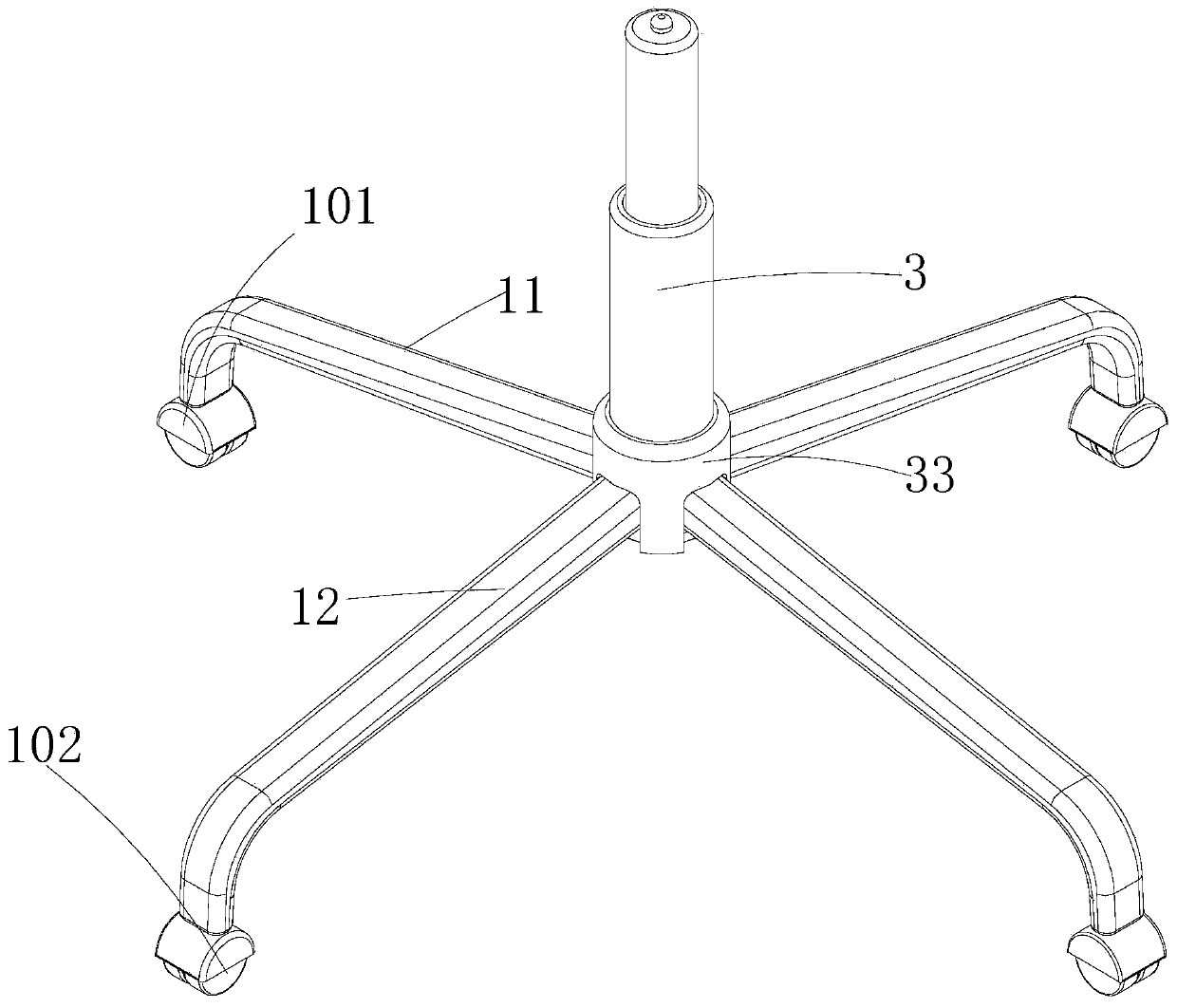
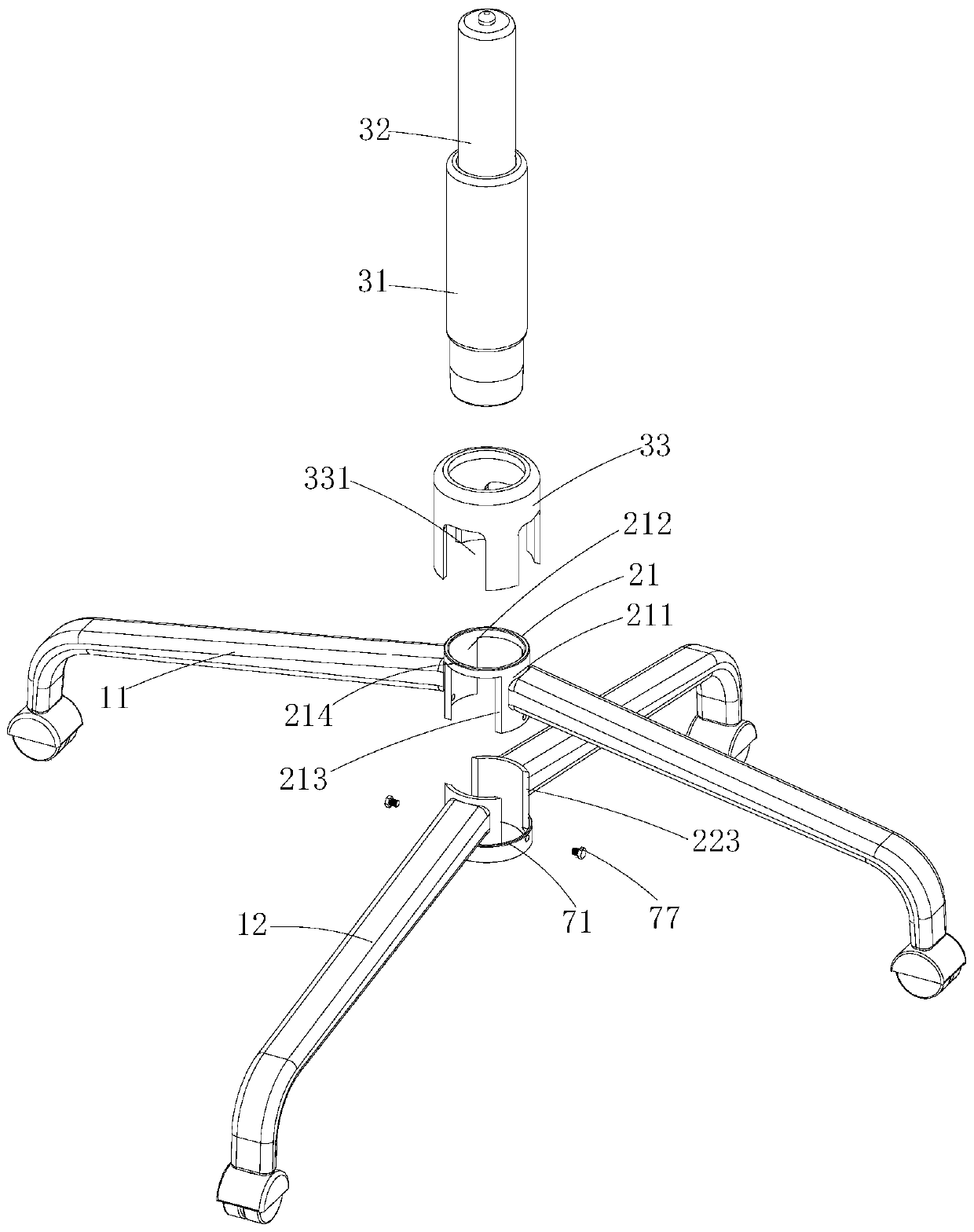
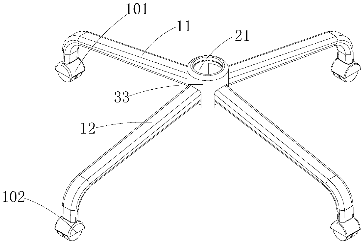
A chair foot and supporting foot technology, which is applied to chairs, other seating furniture, quick-action fasteners, etc., can solve the problems of inability to achieve rapid assembly, increase the cost of seats, reduce boxing efficiency, etc., and achieve a simple structure. , High assembly efficiency, good protection effect
- Summary
- Abstract
- Description
- Claims
- Application Information
AI Technical Summary
Problems solved by technology
Method used
Image
Examples
Embodiment 2
[0042] Such as Figure 5-9 As shown, the difference between this embodiment and Embodiment 1 is that the locking structure in this embodiment is different from that in Embodiment 1. Specifically, the locking structure includes a protrusion 71, a locking member 72, a pushing member 74 and The locking hole 73, wherein the protruding part 71 is the same as the protruding part described in the first embodiment; a mounting groove 710 is provided on the protruding part 71, and the pushing member 74 is arranged in the mounting groove 710 Inside, the pushing member 74 is a spring; the locking member 72 is partially arranged in the installation groove 710, the locking member 72 is a metal ball, and the pushing member 74 can push the locking member 72 to move outward; The locking hole 73 is a circular hole located at the bottom of the first connecting piece 21, when the first connecting piece 21 is inserted into the second connecting piece 22, the locking piece 72 is inserted into the l...
Embodiment 3
[0044] Such as Figure 10-13 As shown, the difference between this embodiment and Embodiment 1 is that the locking structure disclosed in this embodiment is different from Embodiment 1, and the locking structure in this embodiment includes a buckle provided on the inner wall of the second connecting member 22 A convex portion 78, the buckle convex portion 78 is arranged on the lower part of the second connecting piece 22, and a buckling groove 79 is arranged on the outer wall of the first connecting piece 21, and the buckling groove 79 is set on the second connecting piece 22. The lower part of a connecting piece 21 , when the first connecting piece 21 is inserted into the notch 221 , the buckling protrusion 78 will be locked into the buckling groove 79 .
Embodiment 4
[0046] Such as Figure 14-16 As shown, the difference between this embodiment and Embodiment 1 is that the number of the central protrusion 211 disclosed in this embodiment is one, and the number of the notch 221 is also one; and the position-limiting structure includes a position-limiting protrusion 215 and The limiting groove 225, the limiting convex portion 215 can be a protrusion, the limiting groove 225 is a concave portion on the second connecting piece 22; therefore, the limiting convex portion 215 will be inserted into The limiting slot 225 is used to limit disengagement between the first connecting piece 21 and the second connecting piece 22 .
PUM
 Abstract
Description
Claims
Application Information
 - R&D
- Intellectual Property
- Life Sciences
- Materials
- Tech Scout
- Unparalleled Data Quality
- Higher Quality Content
- 60% Fewer Hallucinations
Browse by: Latest US Patents, China's latest patents, Technical Efficacy Thesaurus, Application Domain, Technology Topic, Popular Technical Reports.
© 2025 PatSnap. All rights reserved.Legal|Privacy policy|Modern Slavery Act Transparency Statement|Sitemap|About US| Contact US: help@patsnap.com


