


Quick Research
Generate reliable direction feasibility study reports for your R&D in just a few steps.

Technical Q&A
Discover and master advanced knowledge NOW. Basics, ideas, possibilities, all at once.

Find Solutions
As an expert in R&D theories, this can generate solutions to your technical problems instantly.

Evaluate Feasibility
Analyze your overall solution with one click, know your potential R&D risks in advance.

Monitor Landscape
Get weekly tech updates, stay abreast of the latest tech innovations and key insights.
Multifunctional and portable visual function testing equipment
A detection device and a portable technology, applied in the field of multifunctional portable visual function detection devices, can solve the problems of large occupied space, not easy to carry, and monotonous functions.
- Summary
- Abstract
- Description
- Claims
- Application Information
AI Technical Summary
Problems solved by technology
Method used
Image

Examples
Embodiment 1
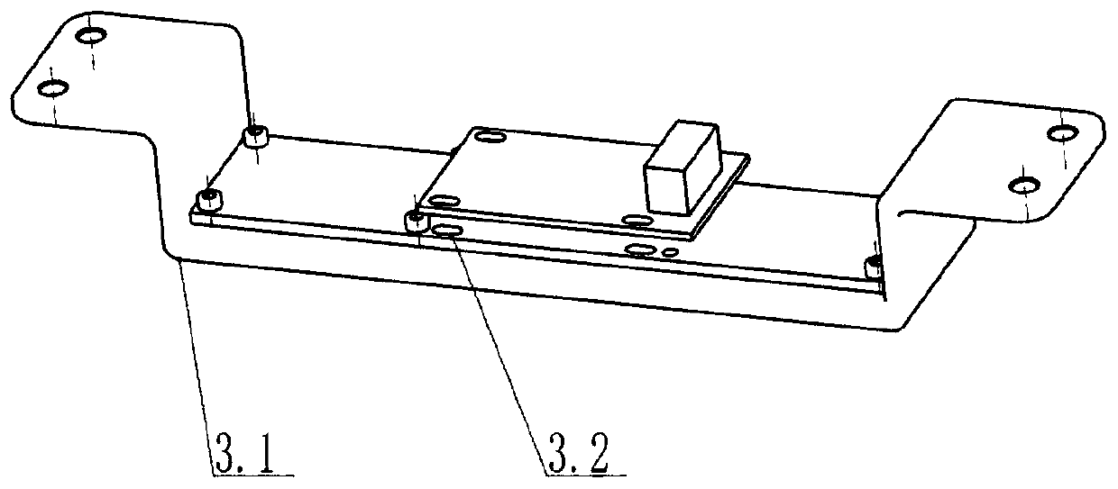
[0056] Vision Test:
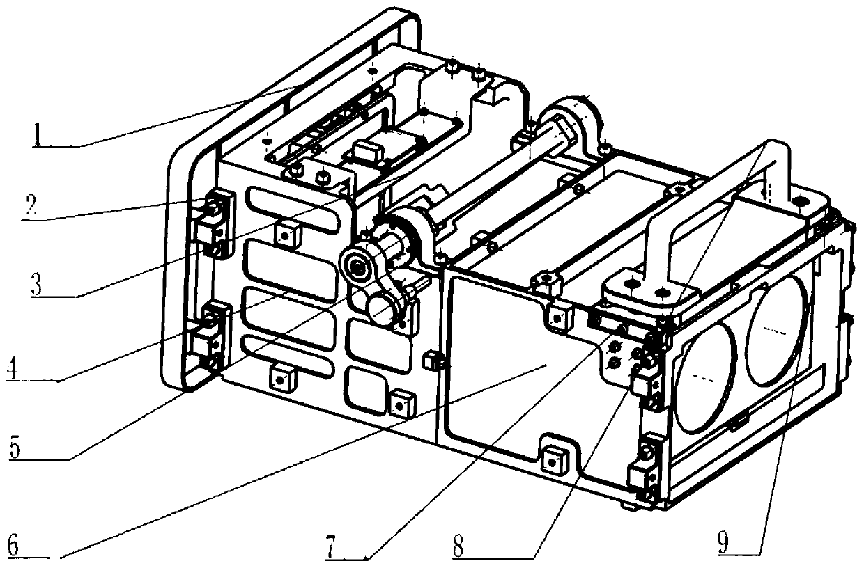
[0057] The optical module 9 is lifted by the handle 8. At this time, the track 9.3 on the optical module 9 slides upward along the sliding seat installed on the front bracket 6, and when it reaches the designed position, it is limited by the stop mechanism 7 to ensure that the optical module 9 will not fall. fall. Reflector 5.4 on the reflective assembly 5 reflects the image formed on the small screen 3.2 to the human eye, and now pull pin 5.1 is in the Figure 7 The preset position 1 in is used to detect the vision function.
Embodiment 2
[0059] Color Vision, Stereo Vision, Contrast Sensitivity, Physiophia Detection:
[0060] Perform pixel adjustment, raise the pull pin 5.1 on the reflection assembly 5, the reflection assembly bracket 5.3 rotates in the bearing seat 5.2, wherein the bearing seat 5.2 has a bearing, and reaches the design position, and the pull pin 5.1 is automatically positioned on the rear support 4 , the automatic positioning process is: set the spring pressure pin, the pressure pin hole and the guide cone hole on the reflection component bracket 5.3, when the user rotates to the position of the guide cone hole, the spring pressure pin will automatically enter the pin hole through the guide cone hole , to achieve pin hole positioning. Pull pin 5.1 is in preset position 2, as Figure 8 shown. The naked-eye large-screen component 1 is switched from an initial small screen with 3.2 pixels to a large screen with 1.2 pixels to realize detection of color vision, stereo vision, contrast sensitivity...
Embodiment 3
[0063] Eyesight detection: the optical module 9 is raised in the front bracket 6 by the handle 8, and when it reaches the designed position, it is limited by the limit mechanism 7 to ensure that the optical module 9 will not be misplaced.
[0064] The reflector 5.4 on the reflection assembly 5 reflects the image on the small screen 3.2 to the human eye through the lens 9.2 on the optical module 9, and the pull pin 5.1 is at the preset position 1, and the human eye sees the virtual image through the optical module 9 at this time , to achieve the detection of 5000mm vision function, such as Figure 9 shown.
PUM
 Abstract
Description
Claims
Application Information
 - R&D Engineer
- R&D Manager
- IP Professional
- Industry Leading Data Capabilities
- Powerful AI technology
- Patent DNA Extraction
Browse by: Latest US Patents, China's latest patents, Technical Efficacy Thesaurus, Application Domain, Technology Topic, Popular Technical Reports.
© 2024 PatSnap. All rights reserved.Legal|Privacy policy|Modern Slavery Act Transparency Statement|Sitemap|About US| Contact US: help@patsnap.com