Cleaning device, cleaning robot, and control method for cleaning device
A technology for cleaning robots and cleaning devices, used in cleaning machinery, cleaning equipment, machine parts, etc., can solve problems such as obstructing the vision of staff, difficulty in replacing or repairing brushes, and small space for brushing operations.
- Summary
- Abstract
- Description
- Claims
- Application Information
AI Technical Summary
Problems solved by technology
Method used
Image
Examples
Embodiment 1
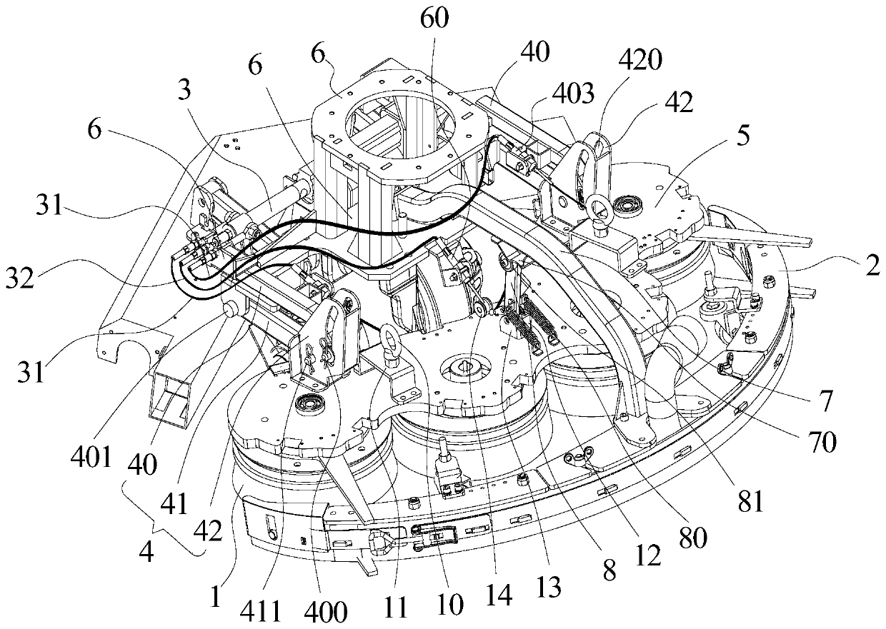
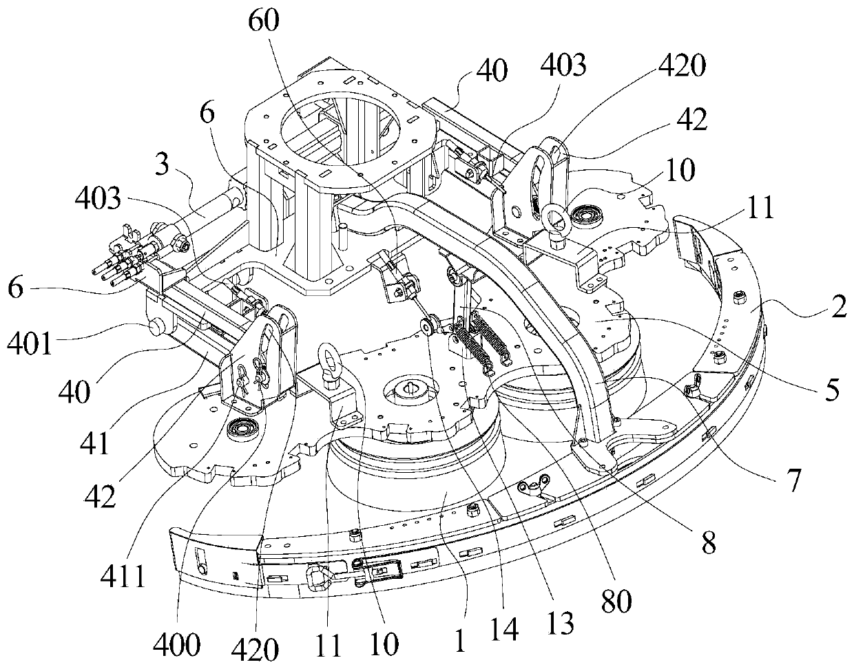
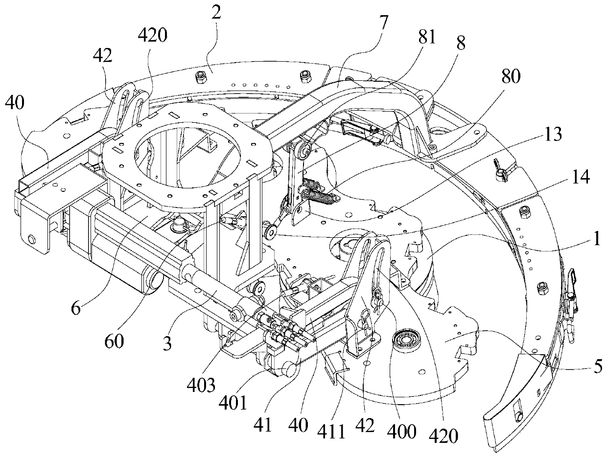
[0049] The cleaning device provided in this embodiment is used for cleaning robots, such as figure 1 , figure 2 with image 3 As shown, the cleaning device includes a brush plate 1, a squeegee 2 and a control unit. The brush plate 1 is located at the front end of the squeegee 2 in the forward direction of the cleaning path. When the brush plate 1 is in a raised state, the control unit can drive the brush plate 1. Incline to the side away from the ground in the opposite direction of the forward direction.
[0050] When the cleaning device is used to clean the ground, the brush plate 1 and the squeegee 2 are both in a lowered state and are in contact with the ground. At this time, the brush plate 1 and the squeegee 2 are both in a working state and can clean the ground.
[0051] When the brush plate 1 in the cleaning device is in an elevated state, there is a space between the brush plate 1 and the ground. At this time, the space between the brush plate 1 and the ground can be prepar...
Embodiment 2
[0106] Picture 11 This is a schematic structural diagram of the cleaning robot provided in this embodiment. The cleaning robot provided in this embodiment includes the cleaning device in the first embodiment. The cleaning robot provided in this embodiment may also include a housing 9 with an opening at the bottom. The drive assembly, transmission assembly and brush plate 1 of the cleaning device are installed in the housing, and the squeegee connecting rod 7 and squeegee 2 are installed in the cleaning device. On the outside of the housing 9.
[0107] The cleaning robot provided in this embodiment includes the cleaning device in Embodiment 1. Therefore, the cleaning robot provided in this embodiment and the cleaning device in Embodiment 1 can solve the same technical problems and achieve the same technical effects.
[0108] The cleaning robot provided in this embodiment also alleviates the existing technology of replacing or repairing the brush plate 1 at the bottom of the existin...
Embodiment 3
[0110] This embodiment provides a method for controlling a cleaning device. The cleaning device includes a brush plate 1, a squeegee 2 and a control unit. The brush plate 1 is located at the front end of the squeegee 2 in the forward direction of the cleaning path. The cleaning device has a normal working state and Maintenance status.
[0111] Among them, in a normal working state, the cleaning device executes the advancing work process, the work to end process, and the work completion process in accordance with it. During the traveling work process, the brush plate 1 and the squeegee 2 are lowered to contact with the ground to clean the ground. When the work is about to end, the brush plate 1 is raised to a raised state set apart from the ground, and the squeegee 2 is still in contact with the ground. During the completion of the work, both the brush plate 1 and the squeegee 2 are raised to a raised state set apart from the ground.
[0112] Wherein, in the maintenance state, the...
PUM
 Abstract
Description
Claims
Application Information
 - R&D Engineer
- R&D Manager
- IP Professional
- Industry Leading Data Capabilities
- Powerful AI technology
- Patent DNA Extraction
Browse by: Latest US Patents, China's latest patents, Technical Efficacy Thesaurus, Application Domain, Technology Topic, Popular Technical Reports.
© 2024 PatSnap. All rights reserved.Legal|Privacy policy|Modern Slavery Act Transparency Statement|Sitemap|About US| Contact US: help@patsnap.com


