


Quick Research
Generate reliable direction feasibility study reports for your R&D in just a few steps.

Technical Q&A
Discover and master advanced knowledge NOW. Basics, ideas, possibilities, all at once.

Find Solutions
As an expert in R&D theories, this can generate solutions to your technical problems instantly.

Evaluate Feasibility
Analyze your overall solution with one click, know your potential R&D risks in advance.

Monitor Landscape
Get weekly tech updates, stay abreast of the latest tech innovations and key insights.
Charging base and cleaning device system
A charging base and cleaning device technology, which is applied to circuit devices, battery circuit devices, coupling devices, etc., can solve problems such as hidden dangers, the charging base cannot be well waterproof and safe, etc.
- Summary
- Abstract
- Description
- Claims
- Application Information
AI Technical Summary
Problems solved by technology
Method used
Image

Examples
Embodiment 1
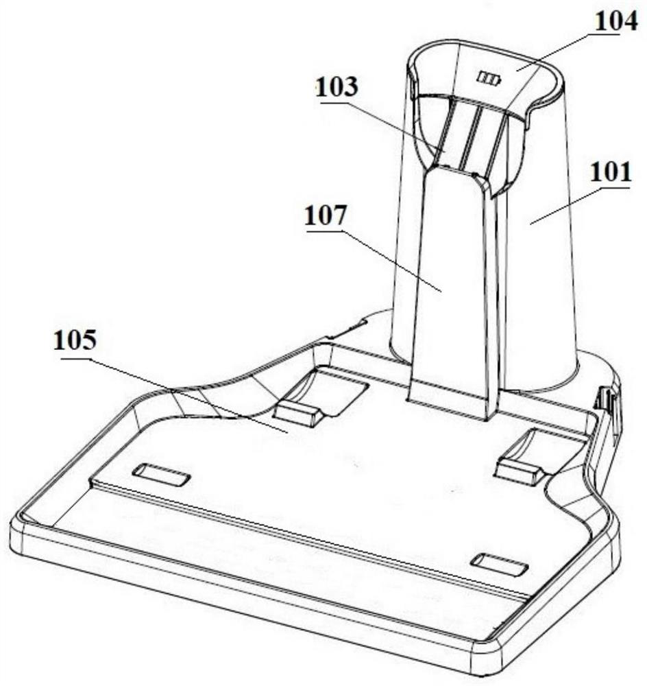
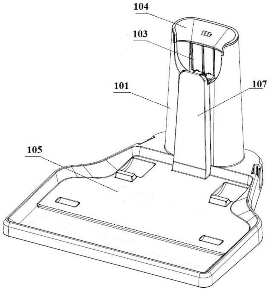
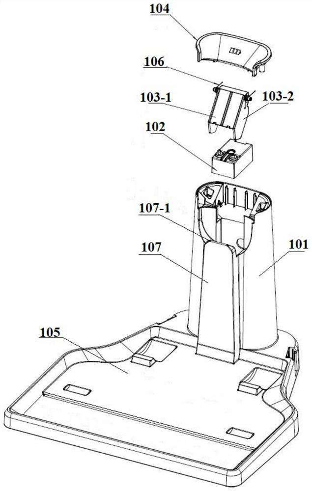
[0042] Embodiment 1 of the present application provides a charging base. In this embodiment, the charging base can charge an electrical appliance while storing the electrical appliance. Such as figure 1 and figure 2 As shown in FIG. 2 , they are schematic diagrams of the structure of the charging base in different states according to Embodiment 1 of the present application. figure 1 It is a schematic diagram of the closed state structure of the baffle mechanism on the charging base, figure 2 It is a structural schematic diagram of the open state of the baffle mechanism on the charging base. At the same time, in order to facilitate the observation of the internal structure of the charging base, the application provides image 3 , which is a schematic diagram of the disassembled structure of the various components inside the charging base.
[0043] In this embodiment, the electrical appliance is a cleaning device, and of course it may also be other rechargeable electrical ...
Embodiment 2
[0064] In the first embodiment above, a charging base is provided for charging electrical appliances. Correspondingly, Embodiment 2 of the present application provides a cleaning device system. Since the charging base in the cleaning device system of this embodiment has been discussed in detail in Embodiment 1, please refer to the implementation for the relevant description of the charging base. The introduction of Example 1 and the following description of the specific structure and working principle of the cleaning device system are only schematic.
[0065] This embodiment provides a cleaning device system, including a cleaning device, and a charging base for charging the cleaning device; the cleaning device is provided with a charging contact sheet for receiving charging;
[0066] The charging base includes a base body and a charging assembly, and a baffle mechanism is arranged above the charging assembly, and the baffle mechanism is used to cover the charging assembly;
...
Embodiment 3
[0069] Corresponding to Embodiment 1, the present application also provides a charging base for charging electrical appliances, including a base body and a charging assembly, the charging assembly including: a base, charging pins, and conductive springs corresponding to the charging pins;
[0070] The conductive spring is nested inside the charging pin, and the upper end of the conductive spring is against the conductive step surface provided on the charging pin (preferably, the conductive step surface is set on the charging pin 102- 2), the lower end leans against the base; the protruding pins of the conductive spring are connected to the electrodes;
[0071] When the electrical appliance is placed on the base body, the conductive spring is in a compressed state, and the upper end of the charging pin abuts and fits with the charging contact piece on the electrical appliance.
[0072] Optionally, the electrical appliance is a cleaning device.
PUM
 Abstract
Description
Claims
Application Information
 - R&D Engineer
- R&D Manager
- IP Professional
- Industry Leading Data Capabilities
- Powerful AI technology
- Patent DNA Extraction
Browse by: Latest US Patents, China's latest patents, Technical Efficacy Thesaurus, Application Domain, Technology Topic, Popular Technical Reports.
© 2024 PatSnap. All rights reserved.Legal|Privacy policy|Modern Slavery Act Transparency Statement|Sitemap|About US| Contact US: help@patsnap.com