Oil remote monitoring system of transformer for power grid operation
A remote monitoring system and power grid operation technology, applied in the direction of instruments, scientific instruments, and testing dielectric strength, etc., can solve problems such as heavy workload, achieve the effects of reducing labor costs, convenient storage, and saving manpower and material resources
Pending Publication Date: 2020-07-03
深圳市资通科技有限公司
View PDF2 Cites 1 Cited by
- Summary
- Abstract
- Description
- Claims
- Application Information
AI Technical Summary
Problems solved by technology
[0005] The disadvantage of the existing technology is that a large amount of data is sent to the general station for summary, and the workload is relatively large
Method used
View moreImage
Smart ImageViewing Examples
Examples
Embodiment
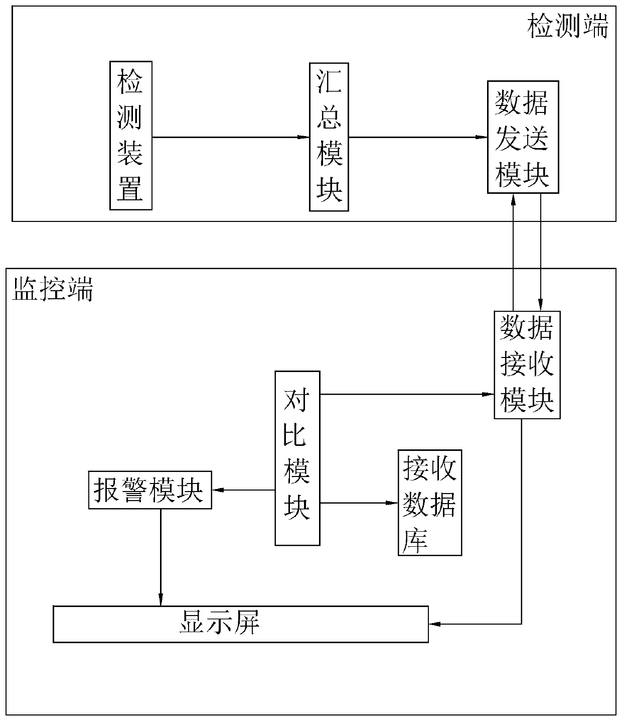
[0033] Embodiment, a kind of oil remote monitoring system of the transformer used for grid operation, refer to figure 1 Set up a detection terminal on multiple substations, set up a monitoring terminal at the headquarters, and set up a detection device for detecting various indicators of transformer oil at the detection terminal, and transmit the data of multiple detection terminals to the monitoring terminal. to monitor.
Login to View More PUM
 Abstract
The invention discloses an oil remote monitoring system of a transformer for power grid operation, and relates to the technical field of monitoring systems. The key points of the technical scheme areas follows: the system comprises a plurality of detection terminals and a monitoring terminal, the detection terminal is provided with a detection device which is used for detecting transformer oil indexes to obtain detection data and sending out detection signals and a data sending module which is in signal connection with the detection device and used for receiving the detection signals and thenremotely sending the detection signals to the monitoring terminal, the monitoring terminal is provided with a data receiving module which is matched with the data sending module and is used for receiving the detection data, and the monitoring terminal is provided with a display screen which is used for displaying the detection data. The system solves the technical problem that the workload is large when a large amount of data is sent to a master station to be gathered, and has the advantage of reducing the workload.
Description
technical field [0001] The invention relates to the technical field of monitoring systems, in particular to an oil remote monitoring system of a transformer used for power grid operation. Background technique [0002] It is a fractionation product of petroleum, and its main components are compounds such as alkanes, naphthenic saturated hydrocarbons, and aromatic unsaturated hydrocarbons. Transformer oil is a mineral oil obtained through distillation and refining of natural petroleum. A mixture of various hydrocarbons. Petroleum-based hydrocarbons include alkanes, naphthenes, aromatics and olefins. [0003] The indicators of transformer oil need to be within a certain range, such as gas content, breakdown voltage, interfacial tension, dielectric loss, furfural, flash point, moisture, water-soluble acid, acid value, volume resistivity, etc. [0004] In the existing technology, the monitoring of various indicators of transformer oil is to install detection devices in substat...
Claims
Login to View More Application Information
Patent Timeline
 Patent Type & Authority Applications(China)
IPC IPC(8): G01N33/28G01R31/12G01N13/02G01N21/31G01N25/52G01N30/02G01N31/16G01N27/06G01N21/25
CPCG01N33/28G01N33/2841G01R31/12G01N13/02G01N21/31G01N25/52G01N30/02G01N31/16G01N27/06G01N21/25
Inventor 李镓于鲜莉李万里贾彦昌
Owner 深圳市资通科技有限公司
Features
- R&D
- Intellectual Property
- Life Sciences
- Materials
- Tech Scout
- Unparalleled Data Quality
- Higher Quality Content
- 60% Fewer Hallucinations
Learn More Browse by: Latest US Patents, China's latest patents, Technical Efficacy Thesaurus, Application Domain, Technology Topic, Popular Technical Reports.
© 2025 PatSnap. All rights reserved.Legal|Privacy policy|Modern Slavery Act Transparency Statement|Sitemap|About US| Contact US: help@patsnap.com


