Metal sheet separation device based on magnetic field

A metal sheet and separation device technology, which is applied in metal processing, metal processing equipment, manufacturing tools, etc., can solve the problems of easily damaged metal sheets, large volume, and high energy consumption, and achieves less error-prone, small size, and low energy consumption. Effect

Inactive Publication Date: 2020-07-03
XIAN AEROSPACE PRECISION ELECTROMECHANICAL INST
View PDF11 Cites 2 Cited by
  • Summary
  • Abstract
  • Description
  • Claims
  • Application Information

AI Technical Summary

Problems solved by technology

[0007] The present invention aims to solve the technical problems of large volume, high energy consumption, error-prone and easy to damage metal flakes existing in the prior art, and provides a metal flake separation device based on magnetic field

Method used


Image

  • Metal sheet separation device based on magnetic field
  • Metal sheet separation device based on magnetic field
  • Metal sheet separation device based on magnetic field

Examples


Embodiment 1

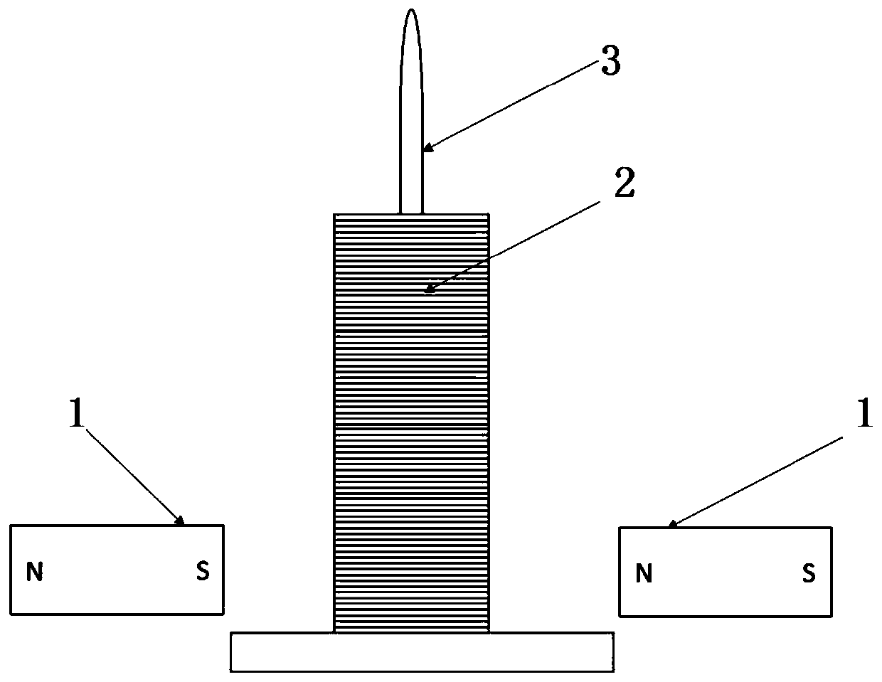
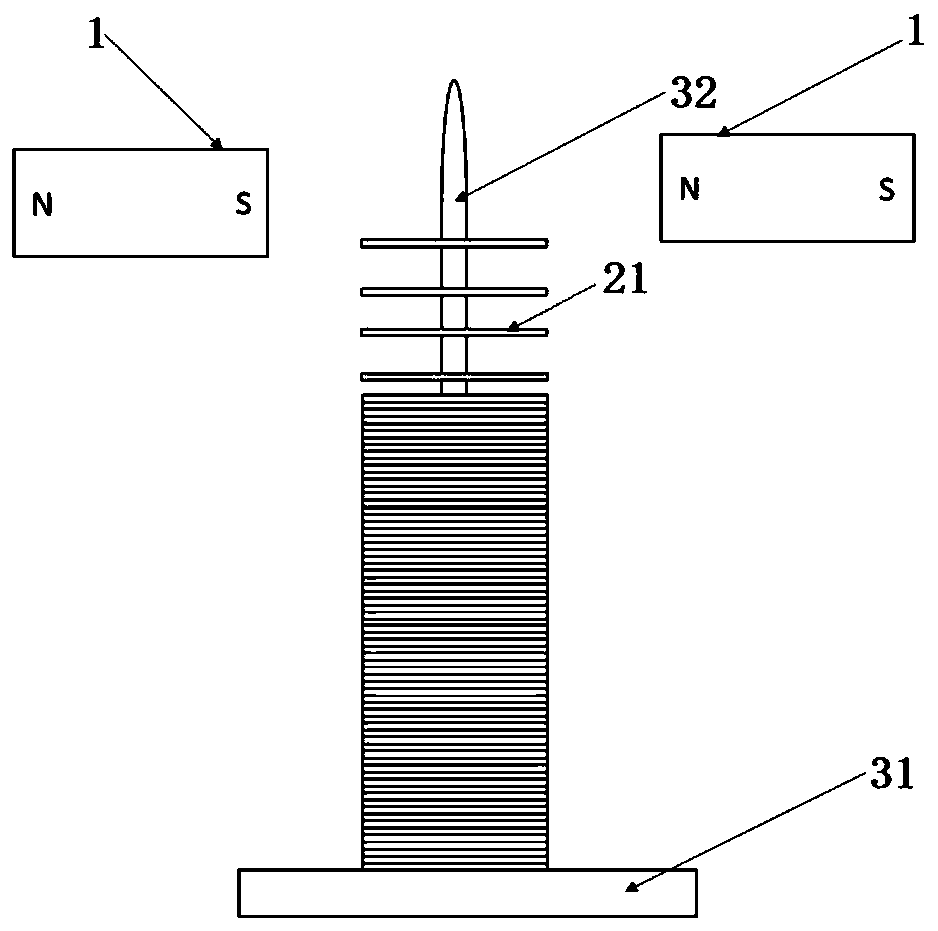
[0043] In this embodiment, a metal flake separation device based on a magnetic field, such as figure 1 As shown, it includes a sheet stacking support 3 and two magnetic field generating units 1; the sheet stacking support 3 includes a stacking platform 31 and a stacking mandrel 32; the stacking mandrel 32 is vertically installed on the stacking platform 31, and a plurality of metal sheets 21 to be separated The superimposed set is placed on the stacking mandrel 32 to form a sheet stack 2; two magnetic field generating units 1 are respectively located on both sides of the sheet stack 2, and each generates a magnetic field; the magnetic poles of the two magnetic fields near the end of the sheet stack 2 are opposite; The magnetic field generating unit 1 is any device that can generate a magnetic field. In this embodiment, it is a permanent magnet. The permanent magnet is the simplest and most convenient, and it can also be an electromagnet.

[0044] When the two magnetic field ge...

Embodiment 2

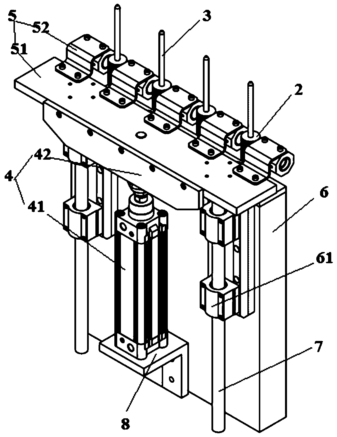
[0046] This example image 3 As shown, several metal flake separating devices as in embodiment 1 are included;

[0047] Also includes a lift unit 4 and a magnet connection assembly 5; the lift unit 4 includes a drive cylinder 41 and a mounting base 42; the drive cylinder 41 is vertically installed on the drive cylinder mounting base 8, and its output end is vertically upward; the mounting base 42 is installed on the drive The top of the output end of the cylinder 41; the magnet connection assembly 5 includes a connecting plate 51 and a plurality of connecting pieces 52; one side of the connecting plate 51 is fixedly installed on the mounting base 42, and a plurality of connecting pieces 52 are evenly arranged along its length direction on the other side The connecting piece 52 is a Z-shaped connecting piece, and can also be an S-shaped connecting piece or an L-shaped connecting piece; one end of the connecting piece 52 is fixedly connected with the connecting plate 51, and the...


PUM


Abstract

The invention discloses a metal sheet separation device based on a magnetic field. The metal sheet separation device aims to solve the technical problems that metal sheet separation equipment in the prior art is large in size, high in energy consumption, prone to errors and prone to damage metal sheets. The metal sheet separation device based on the magnetic field comprises at least one pair of magnetic field generation units, wherein the two magnetic field generation units in each pair of magnetic field generation units are located on the two sides of a sheet stack body formed by stacking a plurality of metal sheets to be separated correspondingly and generate magnetic fields correspondingly, and the magnetic poles of the ends, close to the sheet stack body, of the two magnetic fields areopposite. The metal sheet separation device is simple in structure and small in size, the metal sheets are magnetized through the two magnetic field generation units, then every two adjacent metal sheets repel each other, and under the combined action of repulsive force and gravity, and the plurality of metal sheets located between the two magnetic field generation units can reach a suspended separation state, so that the effect of separation is achieved.

Description

technical field [0001] The invention relates to the separation of metal flakes, in particular to a magnetic field-based metal flake separation device. Background technique [0002] In industrial production, thin steel (iron) parts are commonly used. Generally, these parts are structurally fine-tuned parts that require very precise installation quantities and sizes. Over-installation or missing installation will affect the overall performance. At present, when these parts are taken out, they are all in the form of whole packs and sub-packages. After entering the production site, they are separated and used for structural assembly. Common separation techniques include: vibration separation, mechanical separation, and manual separation. These three separation methods have their own limitations, which bring inconvenience to production. [0003] Vibration separation: special vibration equipment is required, the equipment is large in size, noisy, and consumes a lot of energy, bec...

Claims


Application Information

Patent Timeline
Patent Type & Authority Applications(China)
IPC IPC(8): B23P19/00
CPCB23P19/001B23P19/004
Inventor 晁帅军李佩曹青梅彭小军李靖韩建斌
Owner XIAN AEROSPACE PRECISION ELECTROMECHANICAL INST
Why Eureka
Try Eureka