Adjustable board cutting device
A cutting device and adjustable technology, which are applied to sawing machine devices, metal sawing equipment, metal processing equipment, etc., can solve the problem of consuming a lot of effort, and achieve the effect of simple operation and labor saving.
- Summary
- Abstract
- Description
- Claims
- Application Information
AI Technical Summary
Problems solved by technology
Method used
Image


Examples
Embodiment 1
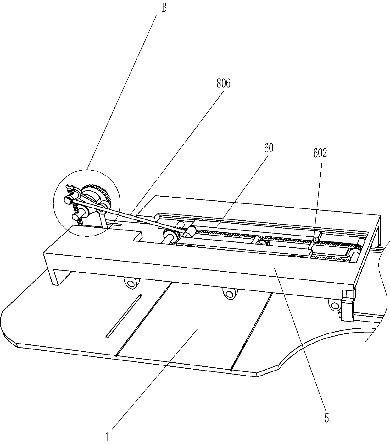
[0028] An adjustable sheet cutting device such as figure 1 , Figure 6 and Figure 7 As shown, it includes a seat board 1 and legs 2, the bottom of the seat board 1 is connected with the legs 2, and also includes a biaxial motor 3, a saw blade 4 and a driving device 7, and the bottom of the seat board 1 is installed with a biaxial motor through bolts 3. One of the output shafts of the biaxial motor 3 is connected with a saw blade 4, and the saw blade 4 passes through the seat plate 1, and the seat plate 1 is provided with a driving device 7.
[0029] The driving device 7 includes a support plate 701, a worm screw 702, a worm wheel 703, a first bevel gear 704, a rotating shaft 705, a second bevel gear 706, a drive gear 707, a sector gear 708, a screw 709, a screw sleeve 710 and a first push rod 711 , a support plate 701 is connected to the top of the seat plate 1, a worm wheel 703 is rotatably connected to the support plate 701, a worm 702 is rotatably connected to the seat p...
Embodiment 2
[0032] On the basis of Example 1, such as Figure 1-5As shown, a transmission mechanism 6 is also included, and the transmission mechanism 6 includes a housing 5, a rack 601, a connecting rod 602, a mounting rod 603, a transmission wheel 604, a toothed belt 605, a rotating rod 606, a first gear 607 and a second gear 607. Gear 608, the top of the seat plate 1 is connected with the housing 5 by bolts, and the rear side of the housing 5 is open. Connecting rod 602, a plurality of mounting rods 603 are rotationally connected between the lower parts of the left and right walls in the housing 5, and transmission wheels 604 are connected to both sides of the mounting rods 603, between the transmission wheels 604 on the left side and the transmission wheel on the right side A toothed belt 605 is wound between 604, and a rotary rod 606 is rotatably connected between the middle parts of the left and right walls in the housing 5, and the left and right parts of the rotary rod 606 are con...
Embodiment 3
[0037] On the basis of Example 2, such as Figure 10 As shown, it also includes a connecting plate 9, a connecting rod 10, a second push rod 11 and a return spring 12. The screw rods 709 on both sides are screwed with the connecting plate 9, and the top of the connecting plate 9 is connected with the connecting rod 10, and the two sides are connected A second push rod 11 is connected between the rods 10, and the second push rod 11 passes through the seat plate 1 and slides with the seat plate 1. A return spring 12 is connected between the connecting plate 9 and the screw rod 709, and the return spring 12 is sleeved on the screw rod. 709 on.
[0038] The screw rod 709 also drives the connecting plate 9 to move together when rotating, and the back-moving spring 12 is compressed. Connecting plate 9 resets under the effect of connecting plate 9, drives second push rod 11 to reset when connecting plate 9 resets, and second push rod 11 resets and promotes plate reset, and like this...
PUM
 Abstract
Description
Claims
Application Information
 - R&D
- Intellectual Property
- Life Sciences
- Materials
- Tech Scout
- Unparalleled Data Quality
- Higher Quality Content
- 60% Fewer Hallucinations
Browse by: Latest US Patents, China's latest patents, Technical Efficacy Thesaurus, Application Domain, Technology Topic, Popular Technical Reports.
© 2025 PatSnap. All rights reserved.Legal|Privacy policy|Modern Slavery Act Transparency Statement|Sitemap|About US| Contact US: help@patsnap.com