
Automatic cooker

A cooking machine and rough surface technology, which is applied in the field of cooking machines, can solve the problems of limited heating area of ​​aluminum foil boxes, complex structure of the whole machine, and limited number of ribs, etc., so as to avoid insufficient mixing of stir-frying, improve the mixing effect of stir-frying, The effect of contact area reduction

Inactive Publication Date: 2020-07-03
JOYOUNG CO LTD
View PDF9 Cites 0 Cited by
  • Summary
  • Abstract
  • Description
  • Claims
  • Application Information

AI Technical Summary

Problems solved by technology

In a kind of cooking equipment, the pot body is movably installed on the device. Before each cooking or after the cooking is completed, the user needs to manually disassemble the pot from the device to clean or serve vegetables, as in the patent CN205514012U applied by the applicant Ribs for stir-frying food are set on the inner tank, however, the number of ribs set is limited and the size is large, so as to facilitate the user to clean and simplify the structure of processing and manufacturing, which makes the food and box in the cooking process The contact area between the body cavity wall or the ribs is large and continuous, and the moisture that will be precipitated during the heating process of the food and the cooking oil in the seasoning will be mixed to generate a large adhesion between the food and the side wall. During the stir-frying process, the ingredients cannot be separated from the side wall, resulting in the sticky surface of the ingredients and the side wall, and the uneven heating of the ingredients, resulting in poor mixing and stirring of the ingredients and affecting the cooking effect
[0003] In addition, an improved cooking machine is provided in the prior art CN207799378U. However, due to the limited heating area of ​​the aluminum foil box, during the cooking process, in order to allow the ingredients to reach their curing temperature, heating tubes are installed on the upper and lower sides of the box body at the same time. , making the structure of the whole machine complex and increasing the cost

Method used


Image

  • Automatic cooker
  • Automatic cooker
  • Automatic cooker

Examples


Embodiment 1

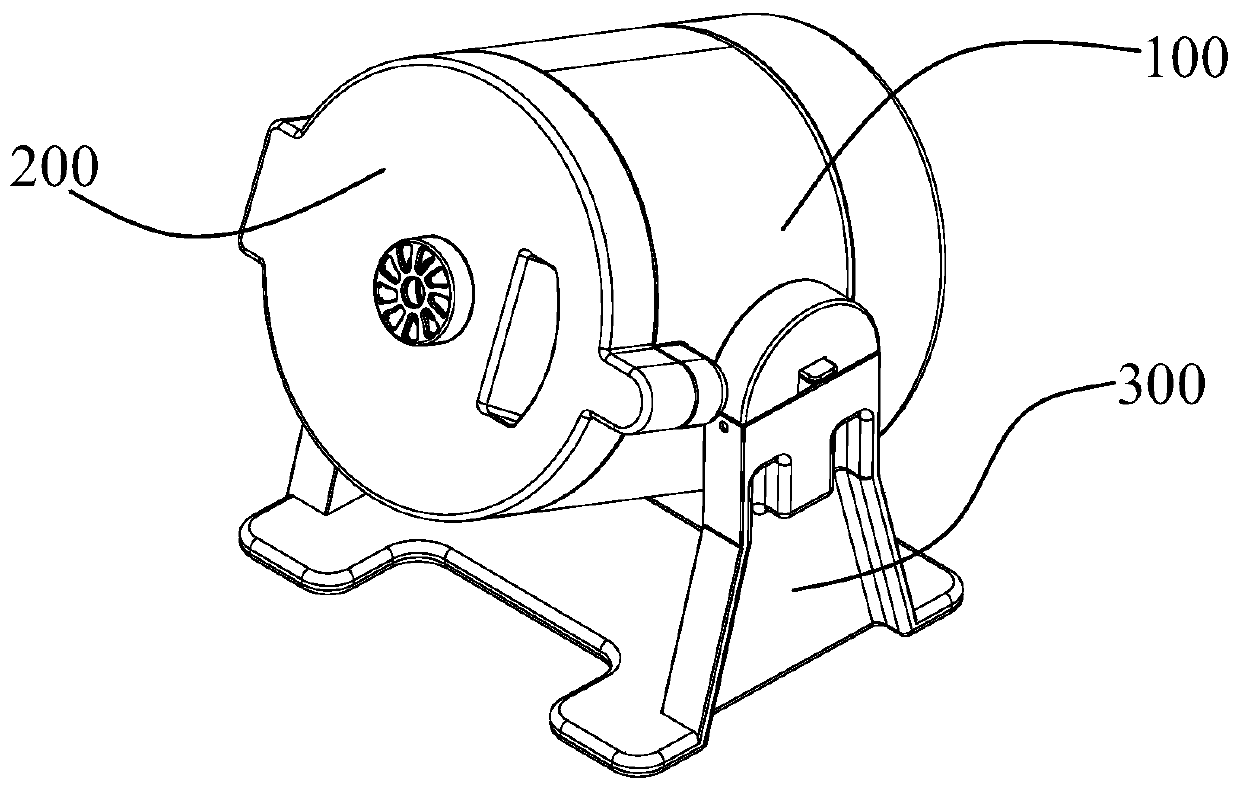
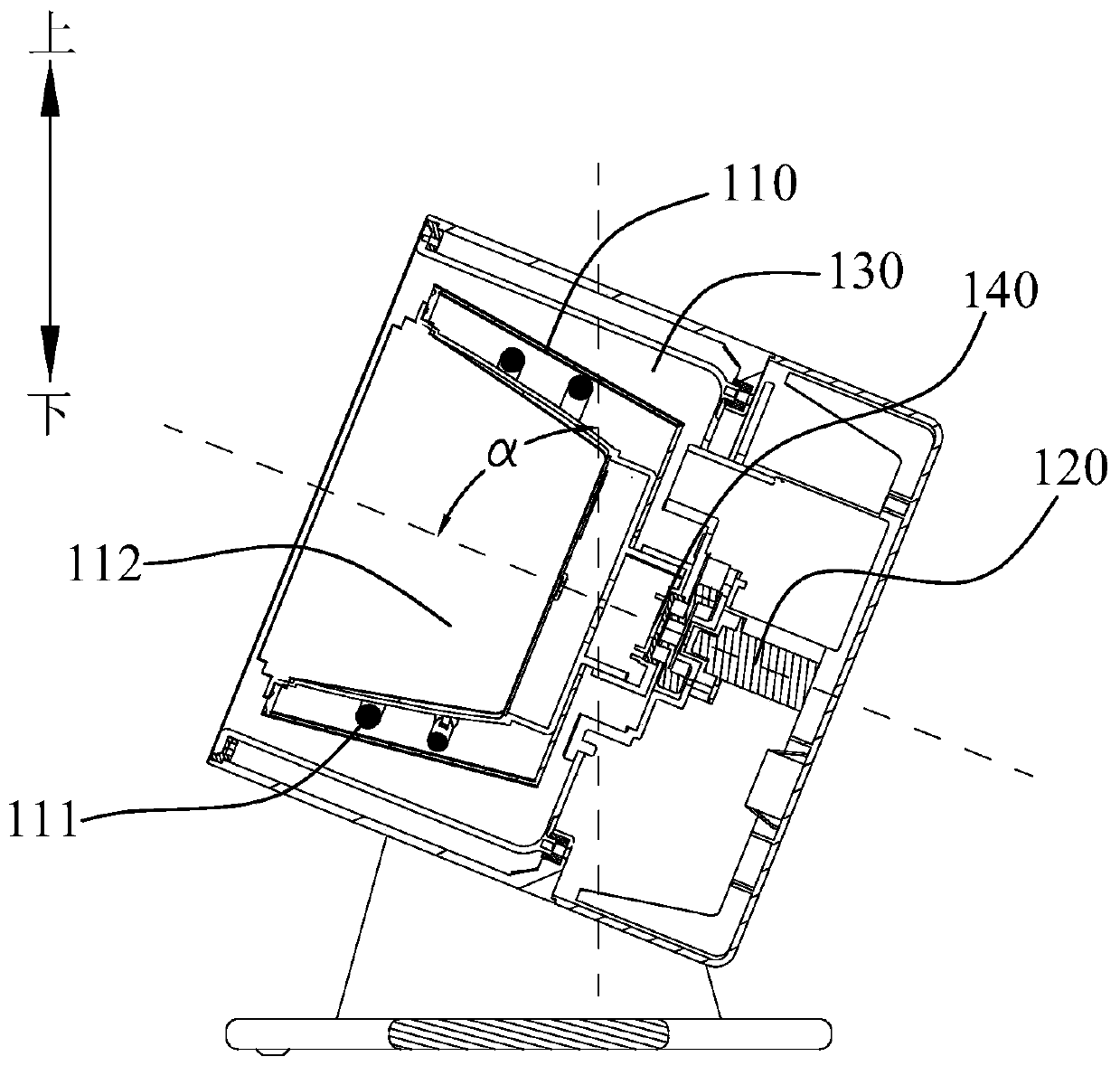
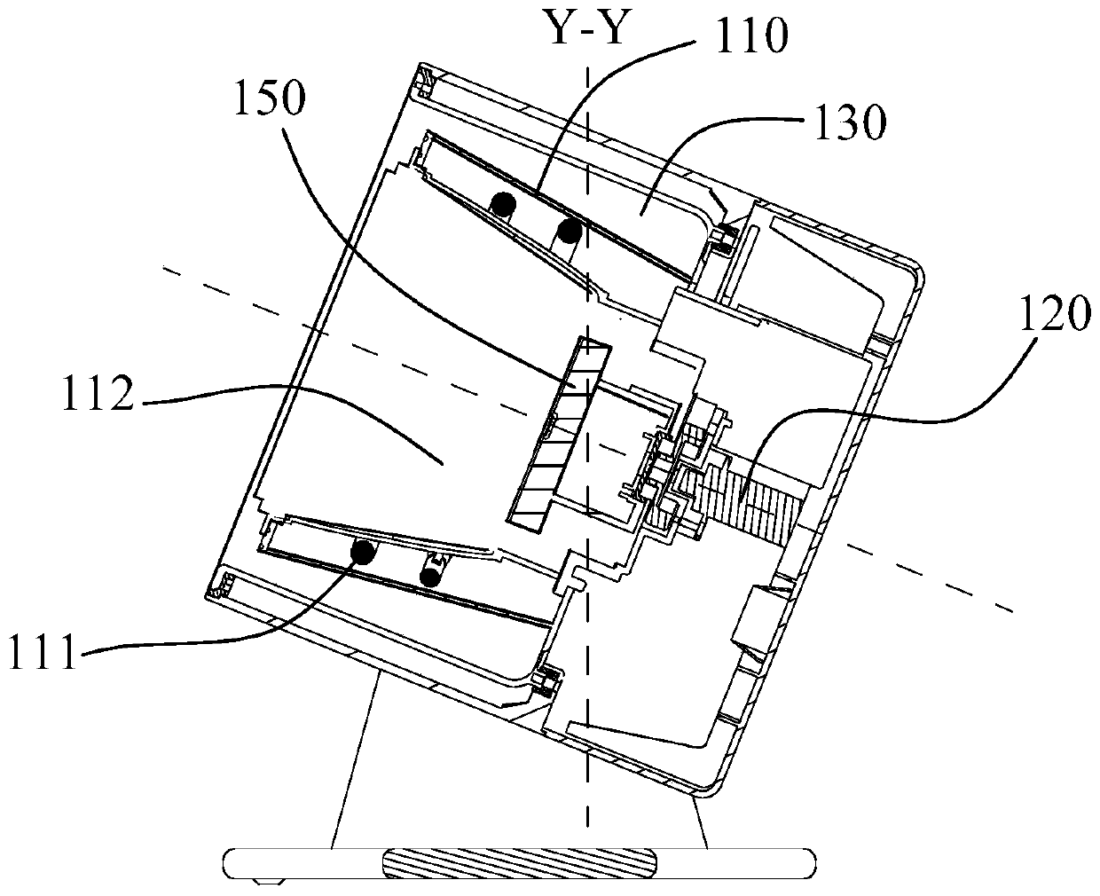
[0051] A kind of cooking machine is provided in the present embodiment, such as figure 1 , 2 As shown, the cooking machine includes a body 100, a cover 200 and a frame 300, the cover 200 is hinged to the body 100, the body is arranged on the frame 300, the body 100 includes a heating cavity 110, The motor 120 and the movable chamber 130, the heating chamber 110 is provided with a heating device 111 and a heating chamber 112 for accommodating the aluminum foil box, the motor 120 is connected with the heating chamber 110 through a connecting device 140, and the motor drives the heating The cavity 110 rotates in the movable cavity 130 of the body. When cooking is required, install the aluminum foil box containing the ingredients in the heating cavity 112 and cover the machine cover, start the heating device 111 to heat the aluminum foil box in the heating cavity 112, driven by the motor 120, The heating cavity 110 drives the aluminum foil box to rotate so as to realize the rot...

Embodiment 2

[0057] This embodiment provides an aluminum foil box used in conjunction with the cooking machine in Embodiment 1. Such as Figure 4 As shown, the aluminum foil box includes a box body 1100 and a cover body 1200. The box body 1100 includes a bottom wall 1110 and a side wall 1120. The bottom wall 1110 and the side wall 1120 form a cavity for dissolving ingredients and an opening 1130. The cover body 1200 is used to close the opening 1130 of the box body, and the inner surface 1121 of the side wall 1120 is provided with a stirring rough surface 1122 formed by folds, and the stirring rough surface 1122 drives the ingredients to stir fry with the rotation of the aluminum foil box.

[0058] Specifically, the folds may be formed during the pressing of the aluminum foil box, or may be pre-treated before pressing, or may be formed in other ways, so that the structure of the pressing mold is simple and the production is convenient.

[0059] It can be understood that the stirring roug...

Embodiment 3

[0096] The difference between this embodiment and the second embodiment is that the folds are only provided on the outer surface of the side wall of the aluminum foil box. Specifically, such as Figure 13 As shown, a heat-absorbing rough surface 1123 formed by wrinkles is provided on the outer surface of the side wall of the aluminum foil box, and the heat-absorbing rough surface 1123 absorbs heat to heat food.

[0097] It can be understood that the heat-absorbing rough surface may be partially disposed on the outer surface of the side wall, or may be disposed covering the outer surface of the side wall.

[0098] By setting the heat-absorbing rough surface formed by folds on the outer surface of the side wall of the box body, the surface area of ​​the aluminum foil box body is increased. During the cooking process, the aluminum foil box body placed in the heating cavity of the cooking machine can absorb / store more The heat can be increased to speed up the cooking and improve ...


PUM

PropertyMeasurementUnit
surface roughnessaaaaaaaaaa

Abstract

The invention provides a cooker comprising a heating cavity for mounting an aluminum foil box and a motor, wherein the aluminum foil box comprises a box body and a cover body, the box body is providedwith a bottom wall and a side wall, the motor drives the aluminum foil box to rotate so that a stirring rough surface formed by wrinkles on the inner surface of the side wall can drive food materialsto be stir-fried, and the included angle between the rotating center axis of the aluminum foil box and the axis perpendicular to the horizontal plane ranges from 0 degree to 75 degrees. By the adoption of the technical scheme, the contact friction force between food materials in the aluminum foil box and the stirring rough surface is increased, the aluminum foil box can drive the food materials to turn over in the rotary stir-frying process, meanwhile, the food materials can be prevented from adhering to the side wall, and the stir-frying mixing effect of the food materials is improved.

Description

technical field [0001] The invention relates to the field of household appliances, in particular to a cooking machine. Background technique [0002] Along with improving constantly of people's quality of life, various equipment that can realize automatic cooking have occurred. In a kind of cooking equipment, the pot body is movably installed on the device. Before each cooking or after the cooking is completed, the user needs to manually disassemble the pot from the device to clean or serve vegetables, as in the patent CN205514012U applied by the applicant Ribs for stir-frying food are set on the inner tank, however, the number of ribs set is limited and the size is large, so as to facilitate the user to clean and simplify the structure of processing and manufacturing, which makes the ingredients and the box in the cooking process The contact area between the body cavity wall or the ribs is large and continuous, and the water that will be precipitated during the heating proc...

Claims


Application Information

Patent Timeline
Patent Type & Authority Applications(China)
IPC IPC(8): A47J27/00
CPCA47J27/002A47J27/004
Inventor 王旭宁郭玉波王国海朱广
Owner JOYOUNG CO LTD
Learn More