
A highly adaptive synchronous rectification control method for a wireless charging receiver

A wireless charging and synchronous rectification technology, applied in electrical components, circuit devices, high-efficiency power electronic conversion, etc., can solve problems such as reducing the rectification efficiency of wireless charging systems, and achieve simple and reliable control circuits, low conduction losses, and rectification. Effects of Features

Active Publication Date: 2020-08-25
CHENGDU YICHONG WIRELESS POWER TECH CO LTD
View PDF8 Cites 0 Cited by
  • Summary
  • Abstract
  • Description
  • Claims
  • Application Information

AI Technical Summary

Problems solved by technology

[0004] The technical problem to be solved by the present invention is to provide a highly self-adaptive wireless charging receiver for the problem that the traditional diode rectifier circuit has a conduction loss caused by the forward conduction voltage drop of the diode, which will reduce the rectification efficiency of the wireless charging system. Synchronous rectification control method, to turn on or off the MOS tube with lower conduction loss through appropriate control method to replace the diode in the traditional diode rectification circuit to obtain higher rectification efficiency

Method used


Image

  • A highly adaptive synchronous rectification control method for a wireless charging receiver
  • A highly adaptive synchronous rectification control method for a wireless charging receiver
  • A highly adaptive synchronous rectification control method for a wireless charging receiver

Examples


Embodiment Construction

[0046] The characteristics and performance of the present invention will be described in further detail below in conjunction with the examples.

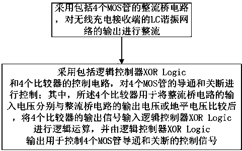
[0047] like figure 2 As shown, this embodiment provides a highly adaptive synchronous rectification control method for a wireless charging receiving end, the method comprising:

[0048] (1) Use a rectifier bridge circuit including 4 MOS tubes to rectify the output of the LC resonant network at the wireless charging receiving end;

[0049]That is to say, in this embodiment, four MOS transistors with lower conduction loss are used to replace the diodes in the traditional diode rectification circuit to obtain higher rectification efficiency.

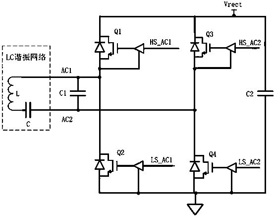
[0050] In one embodiment, such as image 3 As shown, the four MOS transistors are respectively MOS transistor Q1, MOS transistor Q2, MOS transistor Q3 and MOS transistor Q4; wherein,

[0051] The electrical connection point between the drain of MOS transistor Q1 and the source of MOS transisto...


PUM


Abstract

The invention discloses a control method for highly adaptive synchronous rectification for a wireless charging receiving end, and the method comprises the steps: carrying out the rectification of theoutput of an LC resonance network of a wireless charging receiving end through employing a rectifier bridge circuit comprising four MOS transistors; adopting a control circuit comprising a logic controller XOR Logic and four comparators to control the on and off of the four MOS transistors, wherein the four comparators are used for comparing the input voltage of the rectifier bridge circuit with the output voltage or the grounding voltage of the rectifier bridge circuit respectively, output signals of the four comparators are input into the logic controller XOR Logic for logic operation, and the logic controller XOR Logic outputs control signals used for controlling the four MOS transistors to be connected and disconnected. According to the invention, the four MOS transistors with lower conduction loss are turned on or turned off to replace diodes in a traditional diode rectification circuit such that higher rectification efficiency can be obtained.

Description

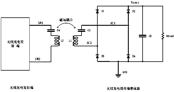
technical field [0001] The invention relates to the technical field of synchronous rectifiers at a wireless charging receiving end, in particular to a highly adaptive synchronous rectifying control method at a wireless charging receiving end. Background technique [0002] In the wireless charging system, the wireless charging receiver converts the alternating electromagnetic energy generated by the wireless charging transmitter into stable DC power through the near-field coupling of the LC resonant network. The process of converting AC power into DC power in a wireless charging system is defined as rectification, and the circuit function module that completes the rectification is defined as a rectifier. [0003] A traditional rectifier consists of 4 diodes such as figure 1 Connect as shown. Among them, the diode rectification circuit composed of diode D1, diode D2, diode D3 and diode D4 rectifies the AC power generated by the wireless charging transmitter into a DC voltage...

Claims


Application Information

Patent Timeline
Patent Type & Authority Patents(China)
IPC IPC(8): H02M7/219H02J50/12
CPCH02M7/219H02J50/12Y02B70/10
Inventor 黎杰王建平王文戴义红李暾梁恩主
Owner CHENGDU YICHONG WIRELESS POWER TECH CO LTD
Learn More