


Quick Research
Generate reliable direction feasibility study reports for your R&D in just a few steps.

Technical Q&A
Discover and master advanced knowledge NOW. Basics, ideas, possibilities, all at once.

Find Solutions
As an expert in R&D theories, this can generate solutions to your technical problems instantly.

Evaluate Feasibility
Analyze your overall solution with one click, know your potential R&D risks in advance.

Monitor Landscape
Get weekly tech updates, stay abreast of the latest tech innovations and key insights.
Camera module positioning method and system based on computer vision
A computer vision and camera module technology, applied in computing, image enhancement, image analysis, etc., can solve problems such as noise points and pixel resolution deviation, and achieve the effects of reducing errors, simple processing, and small amount of processing and compression
- Summary
- Abstract
- Description
- Claims
- Application Information
AI Technical Summary
Problems solved by technology
Method used
Image

Examples
Embodiment 1
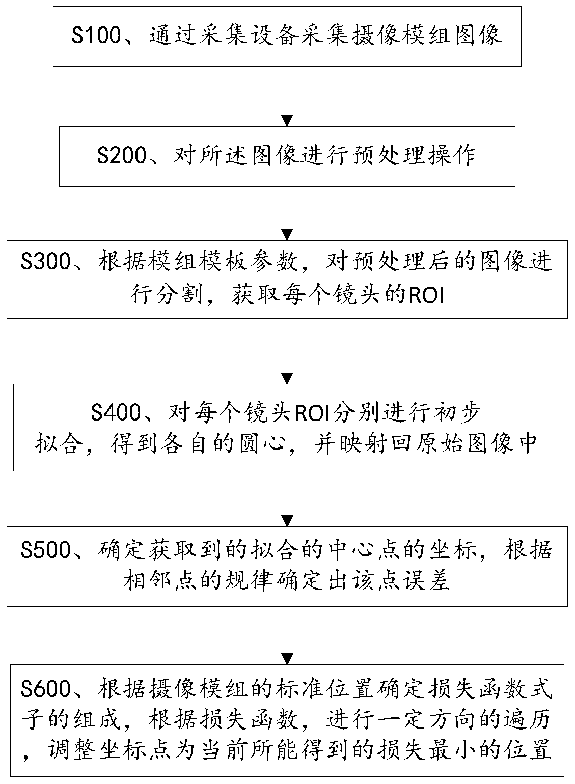
[0035] figure 1 It is a flow chart of a camera module positioning method based on computer vision provided by Embodiment 1 of the present invention, see figure 1 , the method includes the steps of:
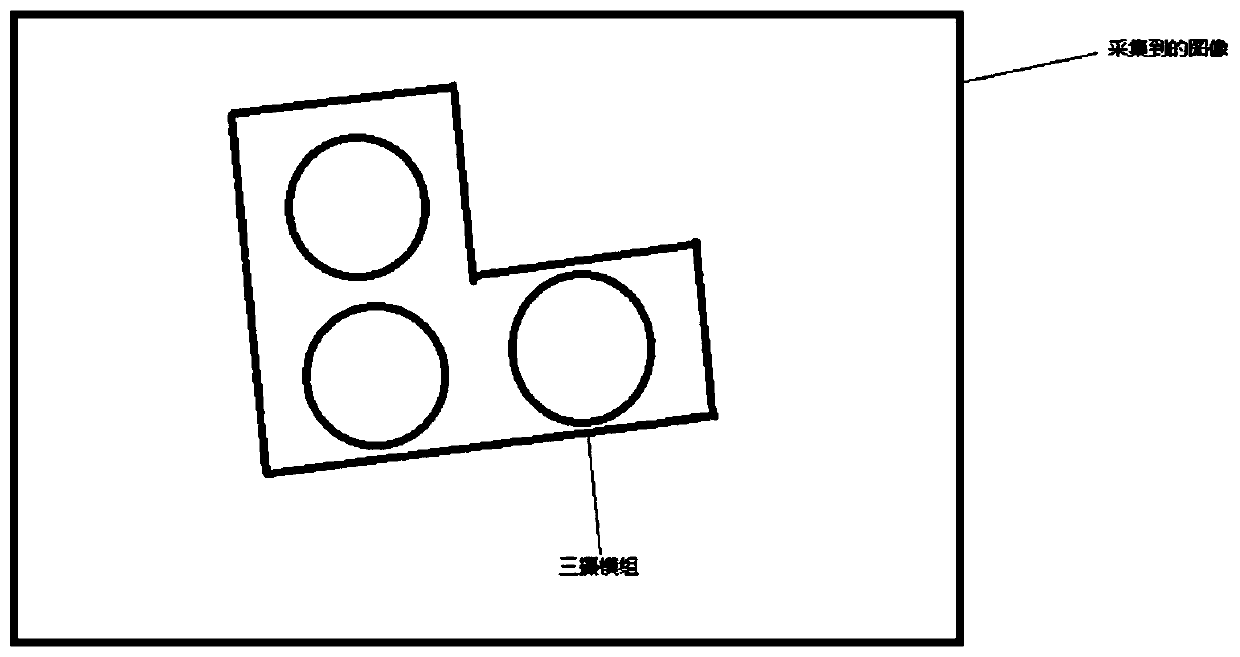
[0036] S100. Collect the image of the camera module through the collection device; figure 2 It is a three-camera module image collected by a collection device such as a high-definition camera provided by Embodiment 1 of the present invention;
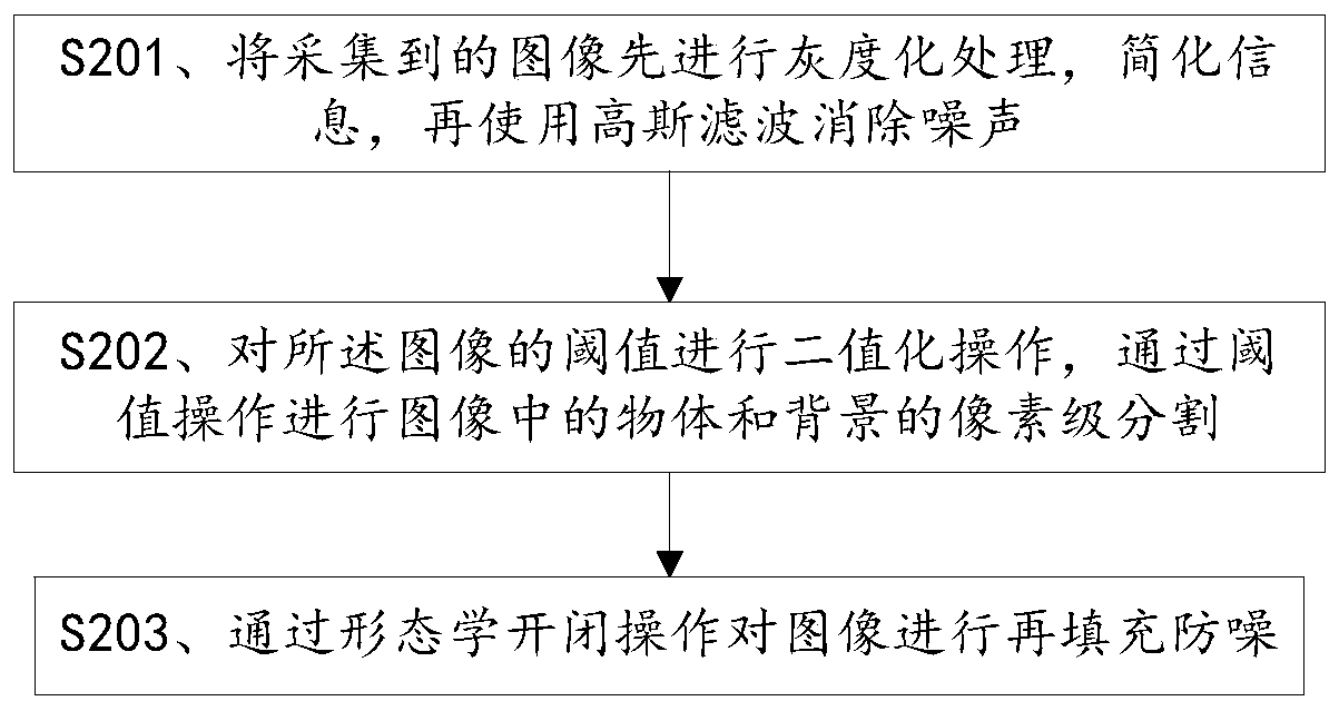
[0037] S200. Perform a preprocessing operation on the image;
[0038] S300. Segment the preprocessed image according to the module template parameters, and obtain the ROI of each shot;
[0039] S400. Preliminary fitting is performed on each lens ROI respectively to obtain respective circle centers, and map back to the original image;
[0040]S500. Determine the obtained coordinates of the fitted center point, and determine the error of the point according to the rules of adjacent points;
[0041] S600. Determine the composition of the...
Embodiment 2
[0079] An embodiment of the present invention provides a camera module positioning system based on computer vision, which is suitable for a camera module positioning method based on computer vision, see Figure 11 , the system includes: an image acquisition module 100, used to collect camera module images through an acquisition device; an image preprocessing module 200, connected to the image acquisition module 100, for performing a preprocessing operation on the image; an image segmentation module 300, connected to the image preprocessing module 200, used to segment the preprocessed image according to the module template parameters, and obtain the ROI of each shot; the preliminary fitting module 400, connected to the image segmentation module 300, using Preliminary fitting is performed on each lens ROI to obtain the respective centers of circles, and are mapped back to the original image; the adjacent point module 500 is determined, and the preliminary fitting module 400 is conn...
PUM
 Abstract
Description
Claims
Application Information
 - R&D Engineer
- R&D Manager
- IP Professional
- Industry Leading Data Capabilities
- Powerful AI technology
- Patent DNA Extraction
Browse by: Latest US Patents, China's latest patents, Technical Efficacy Thesaurus, Application Domain, Technology Topic, Popular Technical Reports.
© 2024 PatSnap. All rights reserved.Legal|Privacy policy|Modern Slavery Act Transparency Statement|Sitemap|About US| Contact US: help@patsnap.com