A high-order modal micromass sensor based on modal localization effect

A localized, high-order mode technology, applied in the field of micro-electromechanical systems, can solve the problems of limiting the application of MEMS devices, high excitation voltage, etc., to achieve the effect of easy driving, improved sensitivity, and wide application

Active Publication Date: 2021-08-03
DALIAN UNIV OF TECH
View PDF0 Cites 0 Cited by
  • Summary
  • Abstract
  • Description
  • Claims
  • Application Information

AI Technical Summary

Problems solved by technology

And we know that for MEMS devices, compared with working in low-order modes, it is generally more sensitive to excite its motion in high-order modes, but because exciting high-order modes is very challenging, it requires a high excitation voltage, which is extremely Greatly limits the application of MEMS devices in high-order modes
Therefore, the same difficulty is faced for weakly coupled structures using mode localization effects

Method used


Image

  • A high-order modal micromass sensor based on modal localization effect
  • A high-order modal micromass sensor based on modal localization effect
  • A high-order modal micromass sensor based on modal localization effect

Examples


Embodiment Construction

[0038]In order to make the purpose, technical solutions and advantages of the embodiments of the present invention clearer, the technical solutions in the embodiments of the present invention will be clearly and completely described below in conjunction with the drawings in the embodiments of the present invention. Obviously, the described embodiments It is some embodiments of the present invention but not all embodiments. The embodiments of the present invention and all other embodiments obtained by persons of ordinary skill in the art without creative efforts all belong to the protection scope of the present invention.

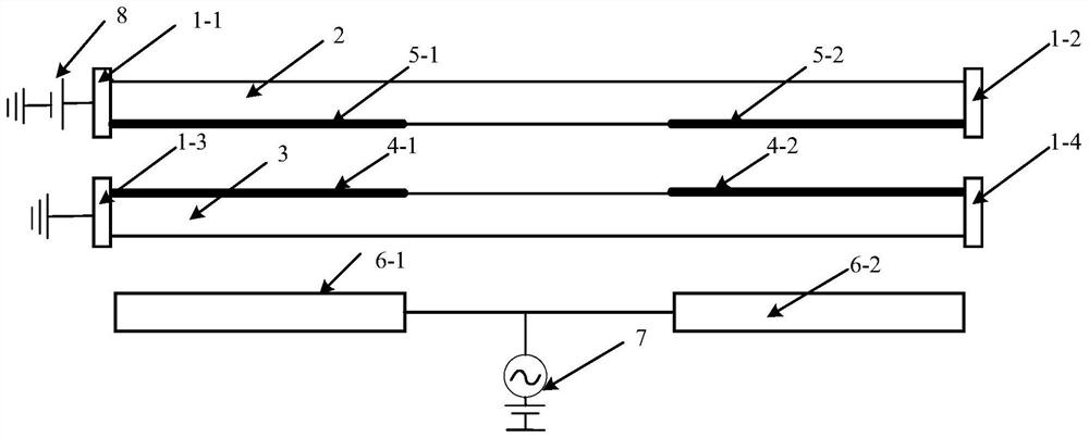
[0039] figure 1 It is a schematic diagram of the high-order modal micromass sensor model based on the modal localization effect of the present invention, a high-order modal micromass sensor based on the modal localization effect, including a first fixed beam 2, a second fixed beam 3, an upper coupling Electrode I5-1, upper coupling electrode II5-2, lower co...


PUM


Abstract

The invention discloses a high-order modal micromass sensor based on the modal localization effect, which belongs to the field of micro-electromechanical systems, and includes a first fixed-support beam, a second fixed-support beam, an upper coupling electrode I, an upper coupling electrode II, a lower coupling electrode Electrode Ⅰ, lower coupling electrode Ⅱ, fixed electrode Ⅰ, fixed electrode Ⅱ, coupling voltage source and driving voltage source; the two ends of the first fixed beam are respectively fixed by fixed end I and fixed end II; the two ends of the second fixed beam are respectively Fixed by fixed end III and fixed end IV; upper coupling electrode I and upper coupling electrode II are fixed on both ends of the lower surface of the first fixed beam; lower coupling electrode I and lower coupling electrode II are fixed on the upper surface of the second fixed beam Both ends of the surface; a coupling voltage source is applied between the lower surface of the first fixed beam and the upper surface of the second fixed beam to realize the corresponding electrostatic coupling connection; the fixed electrode I and the fixed electrode II are respectively connected to the driving voltage source; The fixed electrode Ⅰ and the fixed electrode Ⅱ are fixed under the second fixed support beam. The invention has a simple structure, easy to adjust the driving mode, and does not need any structural optimization. It has the advantages of simple process, stable configuration and easy processing, so it can be widely used. In all aspects.

Description

technical field [0001] The invention relates to the field of micro-electromechanical systems, in particular to a high-order mode micromass sensor based on the mode localization effect. Background technique [0002] Due to its small size, low power consumption, high efficiency and reliability, MEMS resonant sensors have been widely used in micromass sensors, including identification and detection of biomolecules (DNA, cells, bacteria and viruses, etc.), detection of tiny particles and Liquid, gas composition and concentration detection, etc. [0003] Although reducing the size of the sensor can increase the sensitivity, the size cannot be reduced infinitely due to the limitation of the manufacturing process. How to improve the sensitivity of the micromass sensor without changing the structure size has attracted the attention of many scholars. Lochon et al. in "An alternative solution to improve sensitivity of resonant microcantilever chemical sensors: comparison between usin...

Claims


Application Information

Patent Timeline
Patent Type & Authority Patents(China)
IPC IPC(8): G01G3/16G01N5/00
CPCG01G3/165G01N5/00
Inventor 吕明赵剑刘蓬勃
Owner DALIAN UNIV OF TECH
Why Eureka
Try Eureka