
A Bilateral Stitch Control Method for Fully Automatic Computerized Flat Knitting Machine

A computerized flat knitting machine and control method technology, applied in textile and papermaking, knitting, weft knitting and other directions, can solve the problems of complicated control process and inability to effectively eliminate it.

Active Publication Date: 2021-08-24
苏州特点电子科技有限公司
View PDF0 Cites 0 Cited by
  • Summary
  • Abstract
  • Description
  • Claims
  • Application Information

AI Technical Summary

Problems solved by technology

[0003] During the knitting process of the automatic computerized flat knitting machine, rollers are needed to pull the knitted clothes. However, since the rollers are always pulling and the knitting yarn rotates at both sides of the knitted clothes, this will cause the two sides of the knitted clothes to be slightly longer than the middle , this problem is also a problem that has been difficult to solve in the traditional automatic computerized flat knitting machine control
The current solutions to this problem are basically to alleviate the problem by reducing the knitting speed and adjusting the yarn tension, which not only makes the control process complicated, but more importantly, this method cannot effectively prevent the occurrence of the problem

Method used

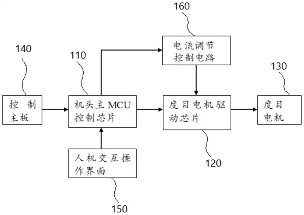
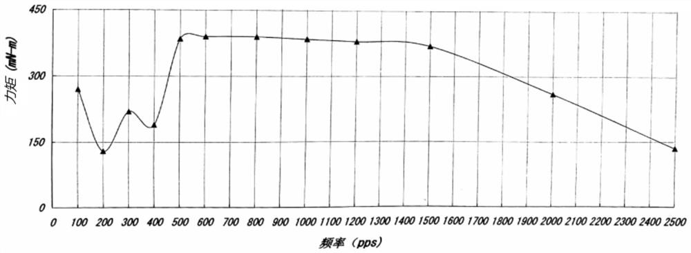
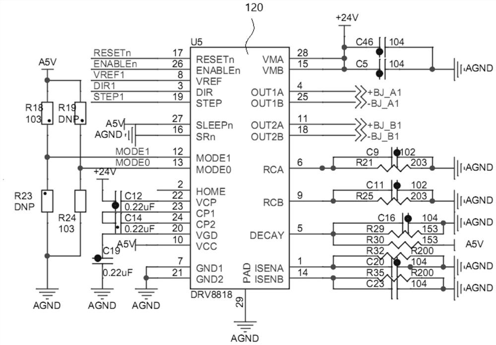

Image

  • A Bilateral Stitch Control Method for Fully Automatic Computerized Flat Knitting Machine
  • A Bilateral Stitch Control Method for Fully Automatic Computerized Flat Knitting Machine
  • A Bilateral Stitch Control Method for Fully Automatic Computerized Flat Knitting Machine

Examples


Embodiment Construction

[0044] The embodiment of the invention discloses a double-sided stitch control method for a fully automatic computerized flat knitting machine. The fully automatic computerized flat knitting machine includes a main MCU control chip of the machine head and a stitch motor drive chip. The adjustment of the needle pressing range is used to realize the adjustment of the coil size of the knitted clothing, and the target position requirement of the stitch change of the knitted clothing is set as: for the same row of knitted clothing, the knitting of the two sides of the row and at least one needle position away from it The stitch value of the segment position is at least 2 characters lower than the preset stitch value of the row of knitted clothes, and the stitch change target position requirements of the knitted clothes are pre-inputted into the main MCU control chip of the machine head; the main MCU control chip of the machine head According to the target position requirement of the...


PUM


Abstract

The invention discloses a double-sided stitch control method for a fully automatic computerized flat knitting machine. The stitch change target position requirement of knitted clothes is set as: for the same row of knitted clothes, the knitting positions of the two sides of the row and at least one needle position away from it are set. The stitch value of the segment position is at least 2 characters lower than the preset stitch value of the knitting clothes in this row, and the stitch change target position requirements of the knitting clothes are pre-inputted into the main MCU control chip of the machine head; the stitch motor driver chip is driven according to the The signal outputs the stitch motor motion curve, which reduces the stitch value of both sides of the woven garment during the movement of the machine head, and is used to eliminate the problem that the sides of the knitted garment are elongated; at the same time, the stitch motor control current is based on the reference voltage PWM output by the main MCU control chip of the machine head. The signal is calculated and determined; the present invention reliably eliminates the problem that the two sides of the knitted clothes are elongated due to the roller traction effect of the computerized flat knitting machine by reducing the stitch value on both sides of the knitted clothes.

Description

technical field [0001] The invention relates to a control technology of a fully automatic computerized flat knitting machine, in particular to a bilateral stitch control method of a fully automatic computerized flat knitting machine. Background technique [0002] The working principle of the fully automatic computerized flat knitting machine is a mechanical device that automatically weaves clothes by designing pattern files through control software. [0003] During the knitting process of the automatic computerized flat knitting machine, rollers are needed to pull the knitted clothes. However, since the rollers are always pulling and the knitting yarn rotates at both sides of the knitted clothes, this will cause the two sides of the knitted clothes to be slightly longer than the middle , this problem is also a problem that has been difficult to solve in the traditional automatic computerized flat knitting machine control. The current solutions to this problem basically alle...

Claims


Application Information

Patent Timeline
Patent Type & Authority Patents(China)
IPC IPC(8): D04B15/36
CPCD04B15/36
Inventor 郝尧尧刘超
Owner 苏州特点电子科技有限公司
Learn More