Motor, motor driving system, electric push rod and electric speed reducer
A technology of motor drive system and screw rod, which is applied in the field of motor and motor drive system, electric reducer, and electric push rod. It can solve the problems of failure to start, affect the accuracy of the motor, and the movement of the shaft, so as to reduce noise and vibration and achieve excellent performance. Motor performance, the effect of eliminating friction loss
- Summary
- Abstract
- Description
- Claims
- Application Information
AI Technical Summary
Problems solved by technology
Method used
Image
Examples
Embodiment 1
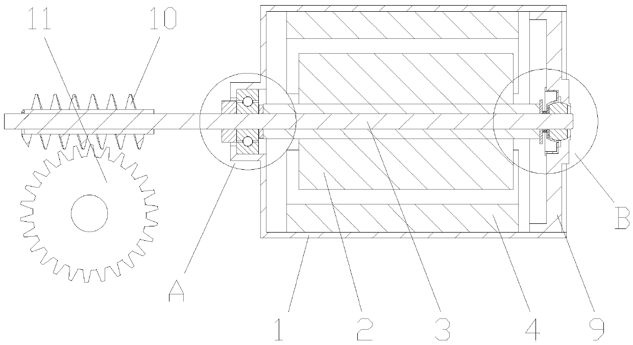
[0030] Embodiment 1: The embodiment of the present invention discloses a motor, such as Figure 1-7 As shown, it is especially suitable for kitchen appliances. The motor drives the worm 11 and drives the worm gear 12 to run, so as to realize the drive of the components in the kitchen appliances.
[0031] Specifically, the motor includes a casing 1 having a front end shaft hole 5 and a rear end shaft hole 901, and the inside of the casing 1 has a rotor assembly 2 and a stator assembly 4; the rotor assembly 2 is a rotating shaft 3 surrounding a coil, and the rotating shaft The two ends of 3 are respectively carried by the front end shaft hole 5 and the rear end shaft hole 901 to realize rotation. The stator assembly 4 is a permanent magnet installed on the inner wall of the housing 1. The magnets are used to surround the outer side of the rotor coil and cooperate with each other; in order to increase For the stability of the rotating shaft 3 during operation, a bearing 6 is inst...
Embodiment 2
[0046] Embodiment 2: The embodiment of the present invention also discloses another kind of motor. The specific structure of the motor is basically the same as that of the above-mentioned embodiment. Different, specifically, in the present embodiment, the shaft sleeve 10 is set to a semi-closed structure, and the outer anti-snag part 702 can be canceled according to the use situation, and the end of the inner hole of the shaft sleeve 10 has a contact surface 101, which can be connected with The axial load of the rotating shaft 3 is supported, and the pressing position between the rotating shaft 3 and the contact surface 101 is located on the axis, which can reduce the friction between the rotating shaft 3 and the contact surface 101 during the rotation process, and reduce the noise and wear of the motor; The anti-channeling part 702 can play a double supporting effect, and the gap between the contact surface 101 and the end face of the rotating shaft 3 is slightly smaller than ...
Embodiment 3
[0049] Embodiment Three: The embodiment of the present invention discloses a motor drive system, such as image 3 As mentioned above, the motor drive system has the motor in the above-mentioned embodiments.
[0050] The motor drive system also includes a worm gear assembly. The worm gear assembly is composed of a worm gear 12 and a worm 11 that are meshed with each other. The worm 11 is installed on the rotating shaft 3. The worm gear 12 can also rotate stably through the shaft support. The rotation of the driven worm 11 through the motor , and then transmitted to the rotation of the worm gear 12 to realize the output of power; on the one hand, the worm gear and worm assembly can realize the deceleration of the rotation and convert it into a larger output torque; force to support, reduce the axial movement of the worm 11 and the rotating shaft 3, reduce the resulting wear and noise, and increase the stability of the entire motor drive system.
PUM
 Abstract
Description
Claims
Application Information
 - R&D Engineer
- R&D Manager
- IP Professional
- Industry Leading Data Capabilities
- Powerful AI technology
- Patent DNA Extraction
Browse by: Latest US Patents, China's latest patents, Technical Efficacy Thesaurus, Application Domain, Technology Topic, Popular Technical Reports.
© 2024 PatSnap. All rights reserved.Legal|Privacy policy|Modern Slavery Act Transparency Statement|Sitemap|About US| Contact US: help@patsnap.com


