
Permanent magnet motor

A technology of permanent magnet motor and electrical angle, applied in the direction of magnetic circuit, electrical components, electromechanical devices, etc., can solve the problems of motor bearings reducing motor life and reliability, and achieve the goal of improving reliability and service life and reducing torque fluctuation Effect

Pending Publication Date: 2020-06-26
大连智鼎科技有限公司
View PDF0 Cites 2 Cited by
  • Summary
  • Abstract
  • Description
  • Claims
  • Application Information

AI Technical Summary

Problems solved by technology

[0003] In order to solve the problem that the method used by the existing motor to reduce the torque fluctuation will bring extra load to the motor bearing and thus reduce the life and reliability of the motor, the invention provides a permanent magnet motor

Method used


Image

  • Permanent magnet motor
  • Permanent magnet motor
  • Permanent magnet motor

Examples


Embodiment Construction

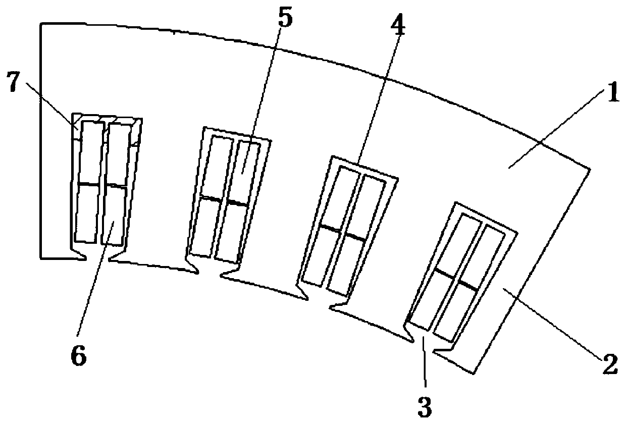
[0015] The permanent magnet motor of the present embodiment comprises a stator and a rotor; the number of rotor poles is 10Y, and Y is a constant; as figure 1 As shown, the stator includes a connected stator yoke 1 and a plurality of stator teeth 2, and the stator teeth 2 are parallel teeth, and trapezoidal stator slots 3 are formed between adjacent stator teeth 2, and the number of stator slots 3 is 12Y, and the stator teeth 2. The coils are wound on top to form two sets of windings, and each stator slot 3 contains the two sets of windings. The stator and the windings are vacuum potted with epoxy resin as a whole. The bottom of the stator slot 4 and the side walls of the slot near the bottom of the stator slot 4 Before the processing goes off-line, the heat-conducting glue 7 is pre-coated, and at least one set of temperature-measuring elements is set in the stator slot 3 to control the current difference in each set of windings according to the temperature value of the tempera...


PUM


Abstract

A permanent magnet motor belongs to the field of motors. The motor comprises a stator and a rotor; the stator comprises a plurality of stator teeth; stator grooves are formed between adjacent stator teeth. N sets of windings are wound on the stator teeth; each stator slot accommodates the N sets of windings; each set of winding comprises M phases of windings, each phase of winding comprises Z coils, 2N coil edges are accommodated in each stator slot, every two coil edges come from one set of winding, and at least one coil edge in the 2N coil edges and the other coil edge located in the same set of winding are different in phase. According to the invention, a winding form is adopted to replace skewed poles and skewed slots, so the torque ripple is reduced, an axial force is not generated, the reliability of the motor is improved, and the service life of the motor is prolonged.

Description

technical field [0001] The invention relates to the field of motors, in particular to a permanent magnet motor. Background technique [0002] In order to reduce the torque fluctuation of the motor and achieve the purpose of reducing the vibration and noise of the motor, the existing motors usually use inclined poles or inclined slots, but this will increase the manufacturing cost of the motor and the complexity of the structure, and the inclined poles and inclined slots will Introduce the axial force of the motor to different degrees, which will bring additional load to the motor bearings, especially for high-power low-speed permanent magnet motors, the generated axial force will be huge, which will seriously reduce the use of bearings life and reliability of the motor. Contents of the invention [0003] In order to solve the problem that the existing method for reducing the torque fluctuation of the motor will bring extra load to the motor bearing, thus reducing the serv...

Claims


Application Information

Patent Timeline
Patent Type & Authority Applications(China)
IPC IPC(8): H02K1/16H02K3/12H02K3/28
CPCH02K1/165H02K3/12H02K3/28H02K2213/03
Inventor 张兆宇刘东旭
Owner 大连智鼎科技有限公司
Learn More