
switchgear or controlgear

A control device and switchgear technology, which is applied in the settings of switchgear, switchgear, and switchgear components, etc., can solve problems such as automation system complexity and weight handling constraints.

Active Publication Date: 2022-03-04
ABB (SCHWEIZ) AG
View PDF9 Cites 0 Cited by
  • Summary
  • Abstract
  • Description
  • Claims
  • Application Information

AI Technical Summary

Problems solved by technology

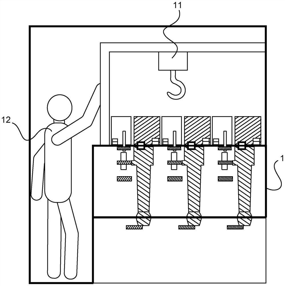
Such robotic systems attempt to mimic how a human operator would access a component, thus entering a switchgear or control gear in a lateral direction to operate, resulting in complexity and weight handling constraints for the automated system

Method used


Image

  • switchgear or controlgear
  • switchgear or controlgear

Examples


Embodiment Construction

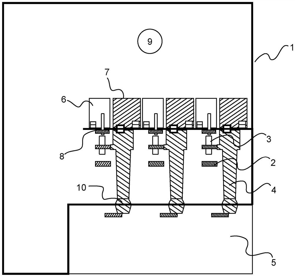
[0055] Figure 1 to Figure 2 An example of a switchgear or control device for operation in a low voltage substation, a medium voltage substation or a high voltage substation is shown.

[0056] One example relates to a switchgear or controlgear, at least one first compartment 1, 5, 9, a plurality of removable modules 6, 7, a plurality of main switchgear or controlgear assemblies, and a plurality of auxiliary switchgear or Control unit components. The plurality of main switchgear or control gear assemblies comprises at least one main busbar system 2, at least one three-position linear or rotary movement disconnector 3, at least one circuit breaker pole 4, and at least one cable connection. The plurality of auxiliary switchgear or control gear assemblies includes at least one disconnect switch driver and at least one circuit breaker driver. A plurality of removable modules are configured to be mounted horizontally within the at least one first compartment at a plurality of hori...


PUM


Abstract

The invention relates to a switchgear or controlgear comprising at least one first compartment, a plurality of removable modules, a plurality of main switchgear or controlgear assemblies, and a plurality of auxiliary switchgear or controlgear assemblies. The plurality of main switchgear or control gear assemblies includes at least one main busbar system, at least one three-position linear or rotary travel disconnect switch, at least one circuit breaker, and at least one cable connection. The plurality of auxiliary switchgear or control gear assemblies includes at least one disconnect switch driver and at least one circuit breaker driver. A plurality of removable modules are configured to be mounted horizontally at a plurality of horizontal positions within the at least one first compartment. A plurality of main switchgear or control gear assemblies are configured to be accommodated in at least one first compartment. A number of auxiliary switchgear or control device assemblies are housed in or associated with the number of removable modules. Each removable module is configured to move vertically from its horizontal position.

Description

technical field [0001] The invention relates to a switchgear or control device for low-voltage, medium-voltage or high-voltage applications in substations. Background technique [0002] In prior art switchgear and control gear (control gear) (also known as control gear) designs, the components requiring maintenance are positioned so that the operator can easily into these parts. Therefore, these components are arranged at different levels stacked on top of each other to facilitate the operator's access to them. This requirement drives the design in which main active switchgear components, such as primary circuits and disconnecting devices, are located at different levels stacked on top of each other. [0003] Robotic systems have been proposed that operate with substations or switchgear or control devices and perform monitoring and maintenance tasks. Such robotic systems attempt to mimic how an operator would access components, thus entering switchgear or controls in a la...

Claims


Application Information

Patent Timeline
Patent Type & Authority Patents(China)
IPC IPC(8): H02B13/00
CPCH02B13/00H02B13/02H02B11/02H02B11/20H02B11/18
Inventor T·科泽尔R·贾沃拉J·塞尔诺豪斯C·布德C·西莫尼迪斯S·沃尔波尼A·阿米迪
Owner ABB (SCHWEIZ) AG
Learn More