
Gate group regulation and control method for realizing local hydraulic scouring of long-distance water conveyance canal

A technology of long-distance water delivery and gates, which is applied in the field of control of gate groups in water conservancy projects. It can solve the problems of long hydraulic transition time and long hydraulic transition time, and achieve the effect of reducing the number of gates and shortening the hydraulic transition time.

Active Publication Date: 2020-06-26
CHINA INST OF WATER RESOURCES & HYDROPOWER RES
View PDF8 Cites 5 Cited by
  • Summary
  • Abstract
  • Description
  • Claims
  • Application Information

AI Technical Summary

Problems solved by technology

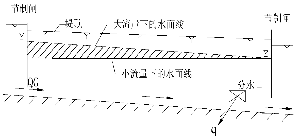
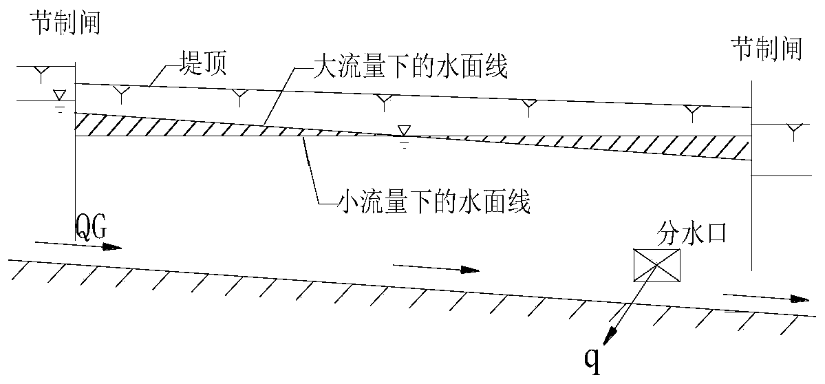
Although it is only necessary to increase the local flow velocity, the changes in flow and water level will be transmitted to the downstream, resulting in the gate group of the entire channel needing to participate in the regulation
Second, the controlled hydraulic transition time is long
Hydraulic scouring includes three processes of increasing flow, maintaining constant flow and reducing flow. Under the operation mode of constant water level in front of the sluice, each channel pool needs to go through the repeated process of first filling and then discharging, and the hydraulic transition time is long.

Method used


Image

  • Gate group regulation and control method for realizing local hydraulic scouring of long-distance water conveyance canal
  • Gate group regulation and control method for realizing local hydraulic scouring of long-distance water conveyance canal
  • Gate group regulation and control method for realizing local hydraulic scouring of long-distance water conveyance canal

Examples


Embodiment Construction

[0030] The specific embodiments of the present invention are described below so that those skilled in the art can understand the present invention, but it should be clear that the present invention is not limited to the scope of the specific embodiments. For those of ordinary skill in the art, as long as various changes Within the spirit and scope of the present invention defined and determined by the appended claims, these changes are obvious, and all inventions and creations using the concept of the present invention are included in the protection list.

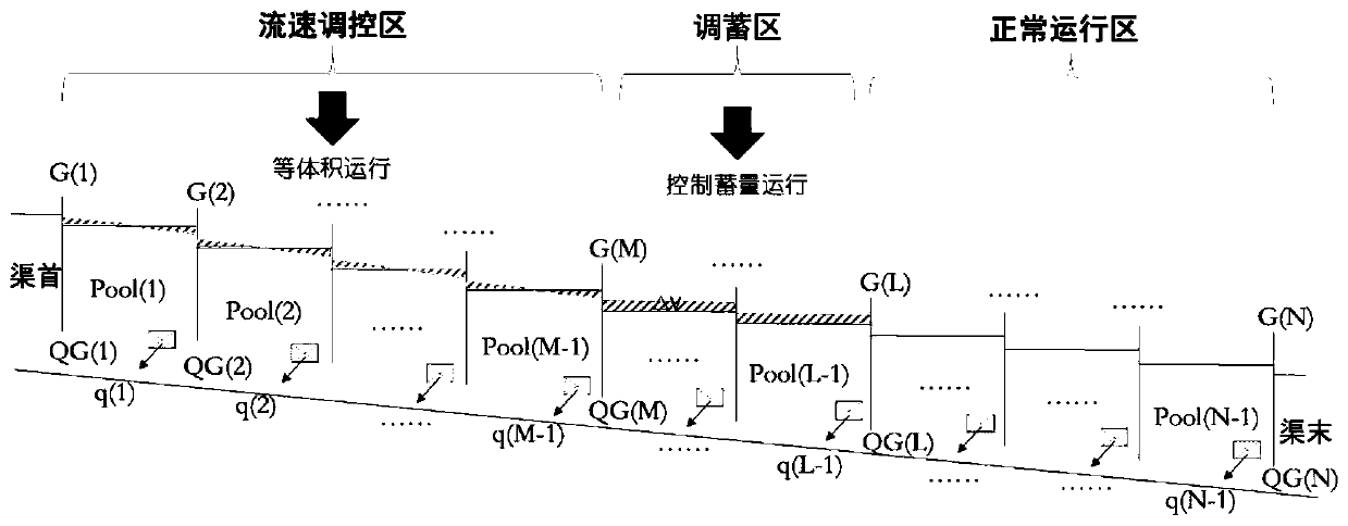
[0031] refer to Figure 4 , Figure 4 A flow chart of a gate group control method for realizing partial hydraulic flushing of a long-distance water delivery channel is given; the method S includes steps S1 to S8.

[0032] In step S1, the hydraulic flushing section to be hydraulically flushed, the flushing duration, and the minimum flushing speed are obtained, and the channel is divided into flow rate control areas includin...


PUM


Abstract

The invention discloses a gate group regulation and control method for realizing channel local hydraulic scouring of a long-distance water delivery channel. The method comprises the following steps: defining channel partitions, and calculating the target flow of each gate in a flow rate regulation and control area and a regulation and storage area; based on the one-dimensional non-constant flow simulation model of the channel, calculating the duration of the flow increasing stage and the duration of the flow decreasing stage in the water filling stage; determining a water filling flow regulation and control scheme of the flow rate regulation and control area in the water filling stage, inputting the water filling flow regulation and control scheme into the one-dimensional non-constant flowsimulation model, judging whether the water level peak value of each canal pool meets conditions or not according to output, if yes, entering the next step, otherwise, expanding the canal pool of theregulation and control area downstream by one, and returning to the target flow calculation step; calculating the duration of the water release stage and the flow regulation and control change valueof each gate in the water release stage, and determining a water release flow regulation and control scheme in the water release stage; and taking the water filling flow regulation and control schemeand the water discharging flow regulation and control scheme which meet the conditions as a gate group regulation and control scheme.

Description

technical field [0001] The invention relates to a gate group control method in water conservancy projects, in particular to a gate group control method for realizing partial hydraulic scour of a long-distance water delivery channel. Background technique [0002] Channels are a common engineering form for long-distance water transportation. In order to raise the water level and adjust the water delivery flow, gates are set at certain intervals to form a series of canals and ponds. For example, in the main canal of the middle line of the South-to-North Water Diversion Project, an average 20km long gate is set up, with a total of 60 canal ponds connected in series. In the control process of the gate group, in addition to limiting the water level within a safe range, it is also necessary to avoid damage to the lining structure caused by excessive water level drop. The usual safety thresholds for water level drop are 0.15m / h and 0.30m / 24h. [0003] As a kind of artificial water...

Claims


Application Information

Patent Timeline
Patent Type & Authority Applications(China)
IPC IPC(8): G06Q10/06G06F30/20
CPCG06Q10/06312
Inventor 崔巍穆祥鹏陈文学刘爽马曼曼刘丰李想
Owner CHINA INST OF WATER RESOURCES & HYDROPOWER RES
Learn More