
Abbe error compensation method and system based on machine tool positioning precision measurement

A technology of Abbe error and positioning error, which is applied in the general control system, control/regulation system, computer control, etc., to achieve the effect of improving the compensation accuracy

Active Publication Date: 2020-06-26
HUBEI UNIV OF ARTS & SCI +2
View PDF8 Cites 9 Cited by
  • Summary
  • Abstract
  • Description
  • Claims
  • Application Information

AI Technical Summary

Problems solved by technology

[0003] The positioning error of the machine tool is a key parameter that affects the machining accuracy of the machine tool parts. Generally, the method of compensating for this error is to measure the positioning error of the machine tool and then directly fill in the measurement results into the compensation module for compensation. This compensation method is used in actual engineering applications. A certain effect can be achieved, but the compensation accuracy still has a lot of room for improvement

Method used


Image

  • Abbe error compensation method and system based on machine tool positioning precision measurement
  • Abbe error compensation method and system based on machine tool positioning precision measurement
  • Abbe error compensation method and system based on machine tool positioning precision measurement

Examples


Embodiment Construction

[0037] In order to make the purpose, features and advantages of the present invention more obvious and understandable, the technical solutions in the embodiments of the present invention will be clearly and completely described below in conjunction with the accompanying drawings in the embodiments of the present invention. Obviously, the following The described embodiments are only some, not all, embodiments of the present invention. Based on the embodiments of the present invention, all other embodiments obtained by persons of ordinary skill in the art without making creative efforts belong to the protection scope of the present invention.

[0038] The technical solutions of the present invention will be further described below in conjunction with the accompanying drawings and through specific implementation methods.

[0039] In general, the device used to measure the positioning accuracy of machine tools is a laser interferometer. The conventional method is to directly compe...


PUM


Abstract

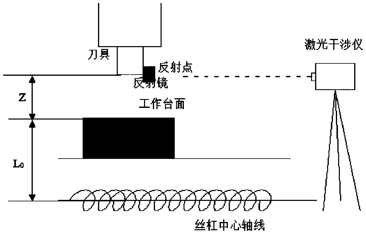
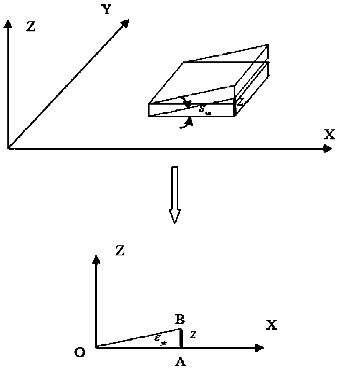
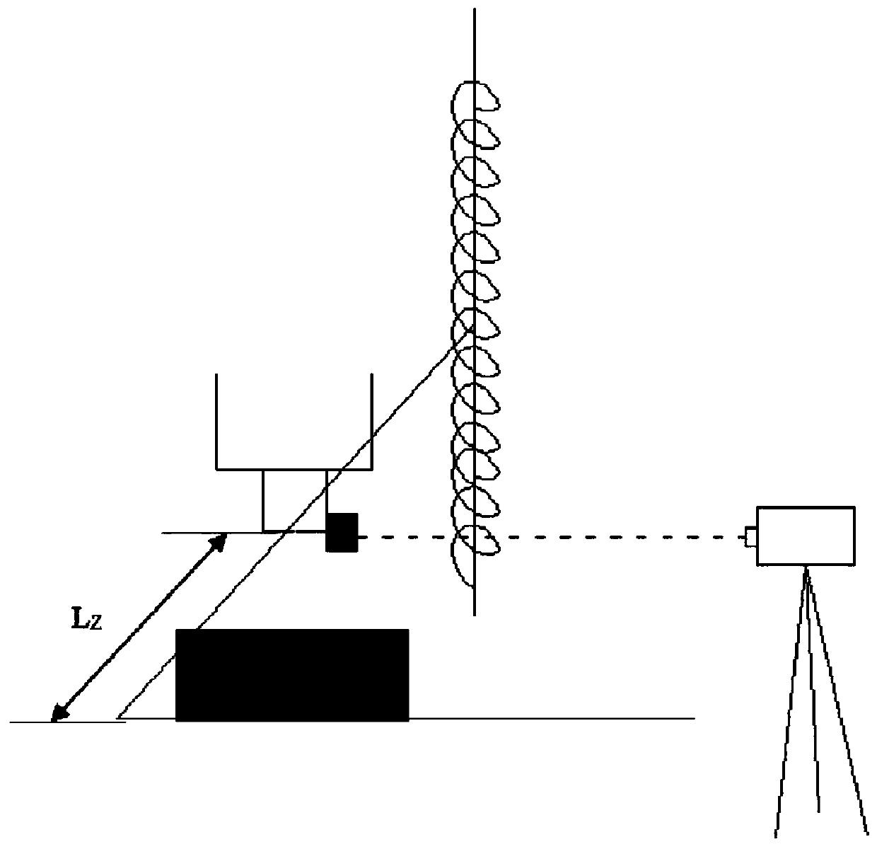
The invention discloses an abbe error compensation method and system based on machine tool positioning precision measurement. The method comprises the steps: arranging a laser interferometer of a measurement device on a machine tool, carrying out the optical debugging, and enabling the laser interferometer to be in a to-be-measured state; recording a measurement program of the numerical control system to enable the program of the numerical control system to be consistent with measurement parameters of the laser interferometer; measuring the positioning error of the machine tool, and generatingan error compensation parameter table; measuring the distance between the emitted light of the laser interferometer and the central axis of the corresponding transmission lead screw, and recording the data as Abbe arm length; and the numerical control system performs superposition operation according to the error compensation parameter table and the abbe error value to generate a compensated positioning error compensation value, and drives the servo motor to perform feeding movement according to the positioning error compensation value to perform error compensation. The method has the advantages that the Abbe error generated in the measurement process is considered, the Abbe error is superimposed on the compensation value to serve as the final positioning precision of the machine tool, and the compensation precision is greatly improved.

Description

technical field [0001] The invention relates to an Abbe error compensation method and system based on machine tool positioning accuracy measurement, and belongs to the technical field of machine tool precision control. Background technique [0002] When CNC machine tools process parts, the accuracy of the machine tool itself is particularly important. Generally speaking, there are many factors in the inaccuracy of CNC machine tools. In order to make the accuracy of the machined parts comparable to or even exceed the accuracy of the machine tool, the method adopted is the method of error compensation. [0003] The positioning error of the machine tool is a key parameter that affects the machining accuracy of machine tool parts. Generally, the method of compensating for this error is to measure the positioning error of the machine tool and then directly fill in the measurement results into the compensation module for compensation. This compensation method is used in actual eng...

Claims


Application Information

Patent Timeline
Patent Type & Authority Applications(China)
IPC IPC(8): G05B19/404G05B19/401
CPCG05B19/404G05B19/4015G05B2219/35408Y02P90/02
Inventor 刘宏伟杨锐向华李波陈国华
Owner HUBEI UNIV OF ARTS & SCI
Learn More