a gas valve

A technology of air valve and valve disc, applied in the direction of balance valve, valve device, valve details, etc., can solve the problem of unreliable air valve drive, and achieve the effect of avoiding instability, fast response and stable response.

Active Publication Date: 2021-09-28
成都特恩达燃气设备有限公司
View PDF12 Cites 0 Cited by
  • Summary
  • Abstract
  • Description
  • Claims
  • Application Information

AI Technical Summary

Problems solved by technology

[0010] The purpose of the present invention is to provide an air valve with over-current protection and over-temperature protection functions, aiming to solve the technical problem of unreliable air valve drive in the prior art

Method used


Image

  • a gas valve
  • a gas valve
  • a gas valve

Examples


Embodiment Construction

[0029] Various exemplary embodiments of the present invention will now be described in detail with reference to the accompanying drawings. It should be noted that the terms "upper", "lower", "front", "rear", "left", "right", "vertical", "horizontal", "top", "bottom" in specific embodiments The orientation or positional relationship indicated by "inner", "outer", etc. is based on the orientation or positional relationship shown in the drawings, and is only for the convenience of describing the present invention and simplifying the description, rather than indicating or implying that the referred device or element must have Certain orientations, constructed and operative in certain orientations, therefore are not to be construed as limitations on the invention.

[0030] In addition, the terms "first", "second", etc. are used for descriptive purposes only, and should not be understood as indicating or implying relative importance or implicitly specifying the quantity of the indic...


PUM


Abstract

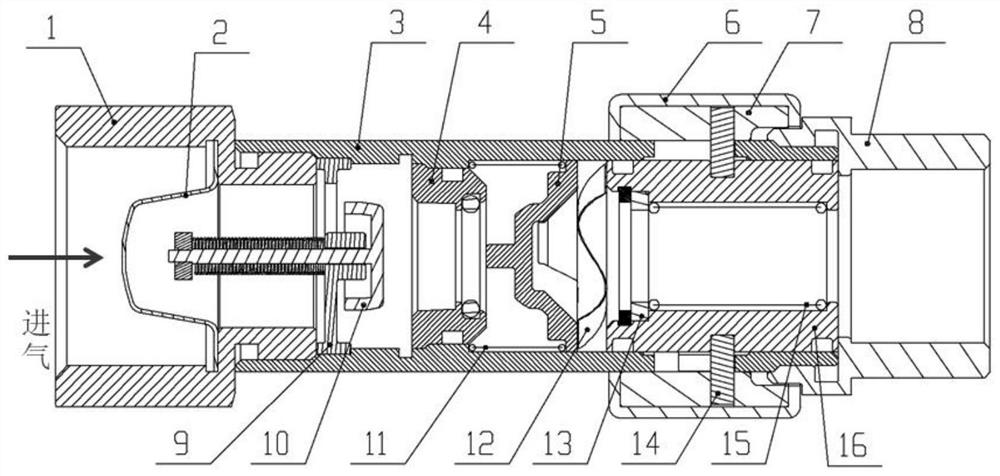
The invention is applicable to the technical field of gas valves, and provides a gas valve with functions of overcurrent protection and overtemperature protection. The temperature assembly structure in the gas valve of the present invention includes a temperature control switch and a third spring, the temperature control switch and the third spring are both arranged inside the valve core, and the third spring is clamped on the positioning structure of the valve core and the temperature control switch Between, when the temperature exceeds a certain value, the temperature control switch will melt, the third spring will lose the limit control and move to the left, and the third spring will directly push the lower disc to move. The invention adopts a mechanical movement mode, which can control the temperature reliably and avoid the unstable defect of the traditional magnetic control; at the same time, when the temperature is high, the spring directly pushes the lower disc to realize sealing, and no other secondary Force transmission, fast response, and stable response; and all moving parts under high temperature conditions are set inside the shell, avoiding unexpected situations that may be stuck by other foreign objects when set outside.

Description

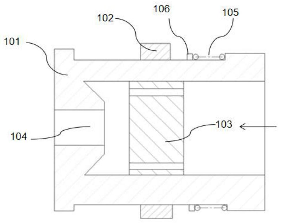
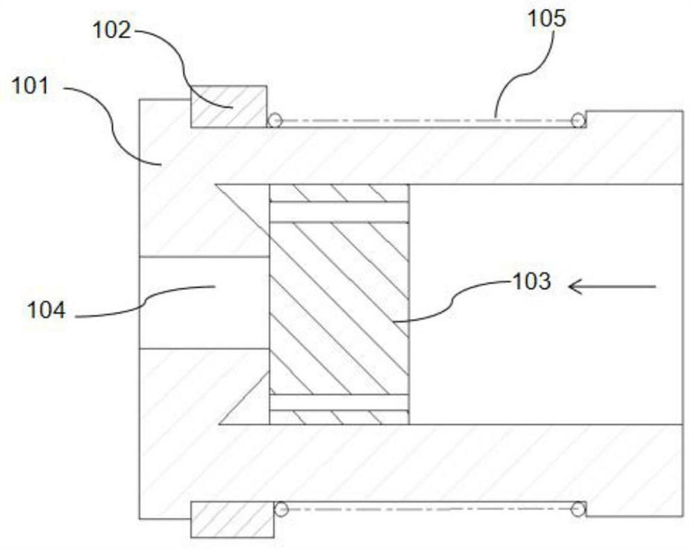
technical field [0001] The invention belongs to the technical field of gas valves, in particular to a gas valve with functions of overcurrent protection and overtemperature protection. Background technique [0002] The gas valve is mainly used for household gas, and it is installed in front of the stove or burning appliance to prevent safety accidents caused by a sudden increase in the gas flow when the flame is turned off, the pipe is broken, or the pipe is taken off; of course, the gas valve can also be installed in other needs Limit the gas flow on the pipeline with excessive flow. [0003] In the prior art, most of the gas valves use magnets and magnetic rings to realize the opening and closing of the valves, such as figure 1 As shown, wherein, the direction of the arrow indicates the air intake direction, and there is a magnetic ring 102 outside the casing 101, the magnetic ring 102 can move left and right on the casing 101, and the airflow passage of the casing 101 ha...

Claims


Application Information

Patent Timeline
Patent Type & Authority Patents(China)
IPC IPC(8): F16K17/04F16K17/168F16K17/38F16K31/60B01D46/24
CPCB01D46/2411F16K17/048F16K17/168F16K17/383F16K31/60
Inventor 何原涛杜仁辉秦浩然
Owner 成都特恩达燃气设备有限公司
Why Eureka
Try Eureka