Connecting structure between locking anchor pipe and steel rack and mounting method thereof

A technology for locking foot anchor pipes and connecting structures, which is applied in the installation of anchor rods, shaft equipment, earthwork drilling and mining, etc. It can solve problems such as solder joints falling off and connection failures, and achieves convenient welding and fixing, increased pull-out resistance, and improved resistance. The effect of bending ability

Inactive Publication Date: 2020-06-26
ERCHU CO LTD OF CHINA RAILWAY TUNNEL GRP +1
View PDF8 Cites 2 Cited by
  • Summary
  • Abstract
  • Description
  • Claims
  • Application Information

AI Technical Summary

Problems solved by technology

[0004] The object of the present invention is to provide a connection structure and installation method between the lock foot anchor pipe and the steel frame, in order to solve the connection method used between the existing lock foot anchor pipe and the steel frame, the solder joints often fall off, and the connection failure problem

Method used


Image

  • Connecting structure between locking anchor pipe and steel rack and mounting method thereof
  • Connecting structure between locking anchor pipe and steel rack and mounting method thereof
  • Connecting structure between locking anchor pipe and steel rack and mounting method thereof

Examples


Embodiment 1

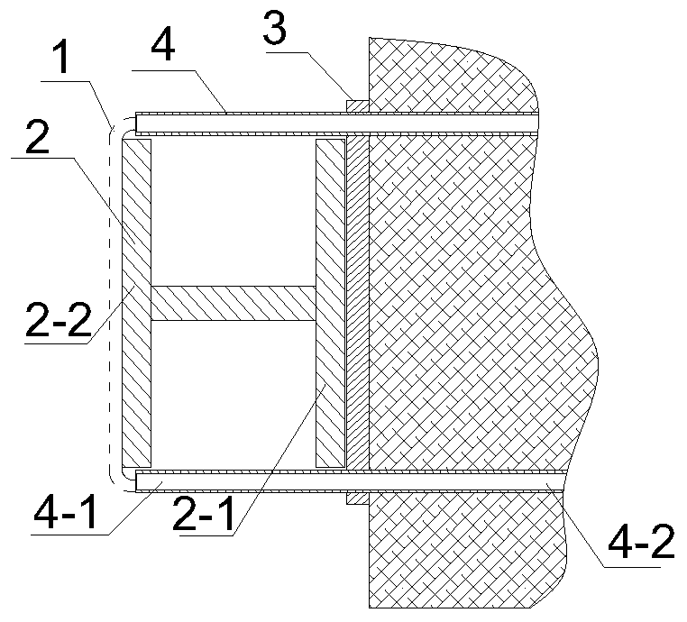
[0041] Such as Figure 1-4 As shown, a connection structure between the locking foot anchor pipe and the steel frame is used for the connection between the locking foot anchor pipe 4 and the steel frame 2, and is characterized in that it includes:

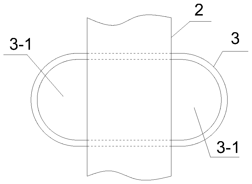
[0042] The ring-shaped steel bar 3 is fixed on the end surface of the steel frame 2 close to the surrounding rock, and a perforation 3-1 is respectively exposed on both sides of the steel frame 2, and two locking foot anchor pipes 4 pass through the two perforations 3-1 respectively;

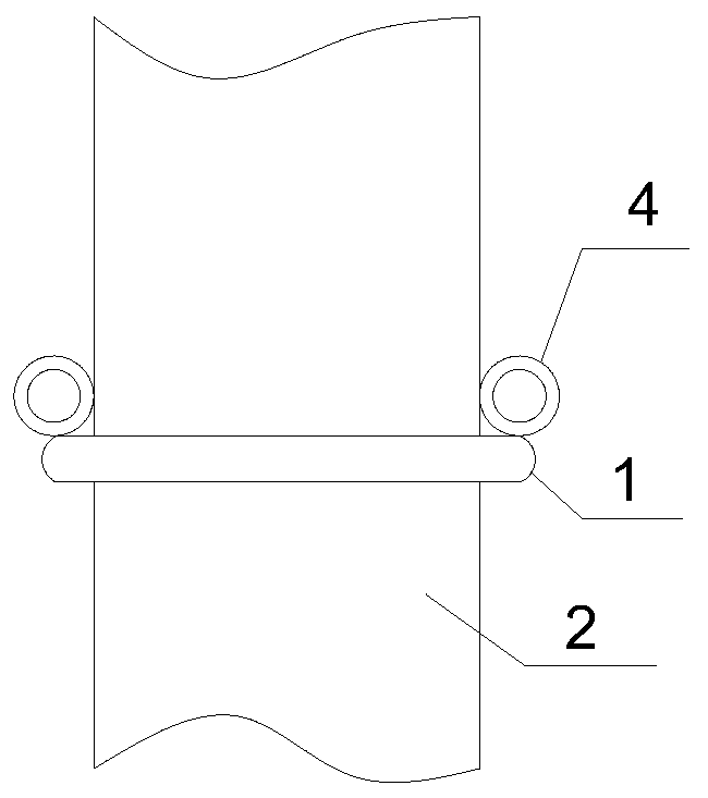
[0043] The connecting steel bar 1 is U-shaped, and the two ends of the connecting steel bar 1 are respectively connected to the outer ends 4-1 of the two locking foot anchor pipes 4 .

[0044] The above-mentioned annular steel bar 3 is welded and fixed to the steel frame 2; In this embodiment, the welding seam between the annular steel bar 3 and the steel frame 2 adopts the surfacing welding method, and the welding seam between the connecting steel ...

Embodiment 2

[0049] In this embodiment, on the basis of Embodiment 1, the device is fixedly connected to the end face of the steel frame 2 away from the surrounding rock, and the connecting steel bar 1 and the steel frame 2 are welded and fixed. The steel frame 2 is an I-beam, and its second wing plate 2-2 away from the surrounding rock is fixedly connected with the connecting steel bar 1, and its welding seam also adopts a surfacing welding method. After the connecting steel bar 1 and the steel frame 2 are welded and fixed, the connecting steel bar 1, the steel frame 2 and the locking foot anchor pipe 4 are combined into a whole, which can cooperate to resist deformation force and pulling force.

Embodiment 3

[0051] Such as Figure 5-7 As shown, in this embodiment, on the basis of Embodiment 2, a limit mechanism 5 is provided at both ends of the annular steel bar 3 of the device, which is used to limit the position of the locking foot anchor tube 4 .

[0052] The limiting mechanism 5 includes a limiting block 5-1, and the hole wall of the perforation 3-1 is provided with a limiting groove 3-2 in shape with the limiting block 5-1, and the limiting block 5-1 is Located in the limit groove 3-2, the cross section of the limit block 5-1 is a right triangle, its right angle face is facing the surrounding rock, and the other right angle face is facing the locking foot anchor pipe 4, and the slope faces the circular steel bar 3. The limiting block 5-1 is provided with a clamping block 5-2 at an acute angle facing away from the surrounding rock, and the clamping block 5-2 prevents the limiting block 5-1 from moving toward the surrounding rock.

[0053] The limiting block 5-1 is in the shap...


PUM


Abstract

The invention discloses a connecting structure between a locking anchor pipe and a steel rack and a mounting method thereof. The connecting structure comprises an annular steel bar and a connecting steel bar, wherein the annular steel bar is fixed to the end surface, close to a surrounding rack, of the steel rack, perforated holes are exposed in two sides of the steel rack, separately, and two locking anchor pipes penetrate the two perforated holes, separately; and the connecting steel bar is U-shaped and two ends of the connecting steel bar are separately connected to the outer ends of the two locking anchor pipes. The connecting structure has the advantages that as the annular steel bar is welded to a wing plate outside the steel rack, the length of a suspending arm end of each locking anchor pipe is shortened, so that the anti-bending ability of the suspending arm end of each locking anchor pipe is improved in a disguised manner, and therefore, the ability of resisting settlement deformation of each locking anchor is improved greatly. By adopting the U-shaped connecting steel bar, the locking anchor pipes on two sides are stressed synergically, so that the pulling resistance ofeach locking anchor pipe is increased and the ability of resisting convergence and deformation of an initial supporting structure is improved. The ability of resisting convergence and deformation of an initial supporting structure is improved comprehensively by adopting a combination system of the annular steel bar and the connecting steel bar.

Description

technical field [0001] The invention relates to the field of tunnel construction and underground engineering construction, in particular to a connection structure between a lock foot anchor pipe and a steel frame and an installation method thereof. Background technique [0002] In the construction of soft rock tunnels, especially the large deformation tunnels under the action of high ground stress, each part of the initial support often has the characteristics of fast convergence and settlement and large deformation before closing and forming a ring. Before the strength of the initial support concrete is formed and the initial support is closed into a ring, the lock-foot anchor tube is a very effective and easy-to-operate measure to control the deformation of the structure, but the specific lock-foot anchor tube is not given in the existing codes According to the construction and quality requirements, the design drawings often only require the use of locking foot anchor pipe...

Claims


Application Information

Patent Timeline
Patent Type & Authority Applications(China)
IPC IPC(8): E21D11/14E21D20/00
CPCE21D11/14E21D20/00
Inventor 唐绍武许永震王治才杨铁伦李志军于家武洪开荣陈伟祥魏小军晏鹏博李鑫郭振枝周希涛杨战锋陈杰华艾小弟王秋林魏立李社伟赵宝锋
Owner ERCHU CO LTD OF CHINA RAILWAY TUNNEL GRP
Why Eureka
Try Eureka