Supergravity dust removal device
A dust removal device and supergravity technology, which are applied in the separation of dispersed particles, chemical instruments and methods, separation methods, etc., can solve the problems of large pressure loss, low dust removal and separation efficiency, and poor effect, and achieve small pressure loss and dust removal and separation efficiency. high, good effect
- Summary
- Abstract
- Description
- Claims
- Application Information
AI Technical Summary
Problems solved by technology
Method used
Image

Examples
Embodiment 1
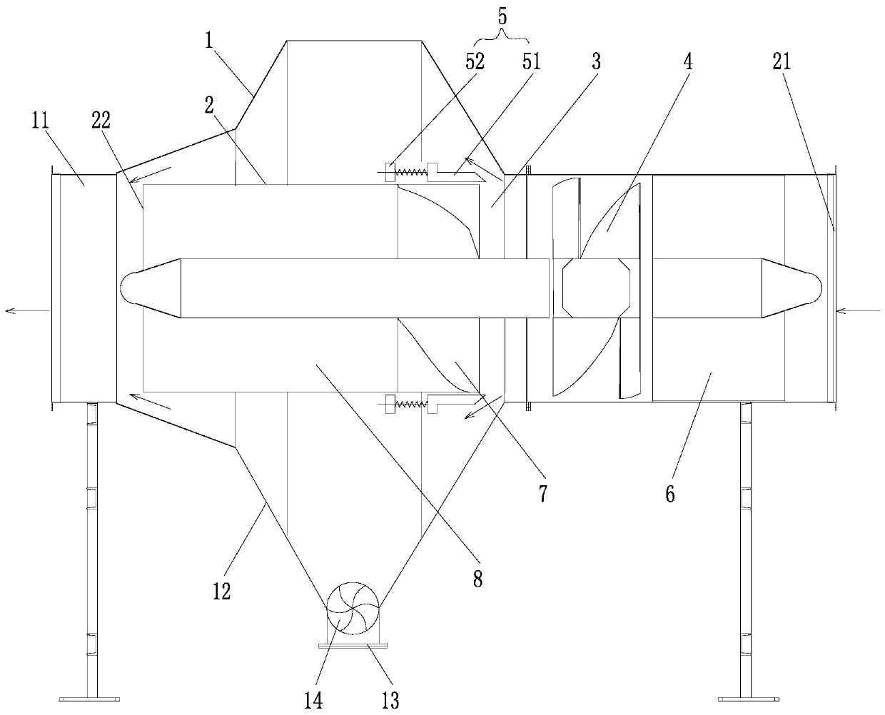
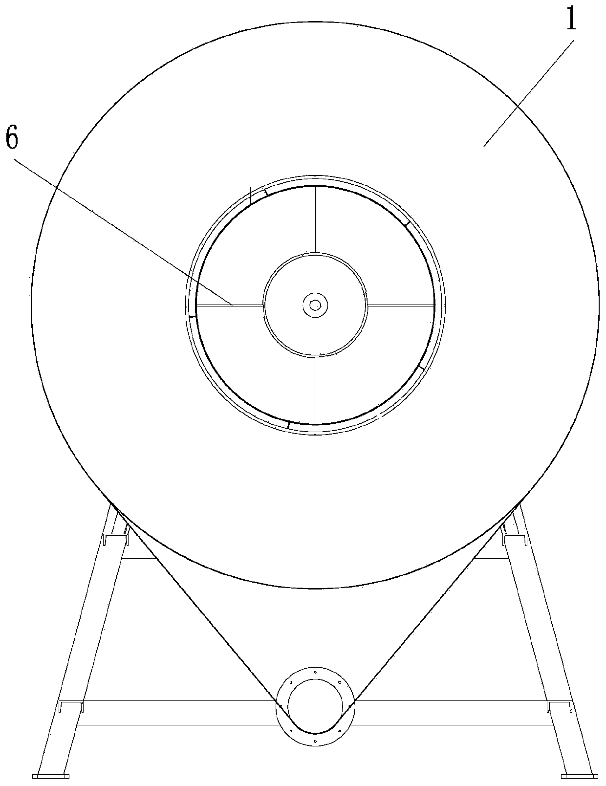
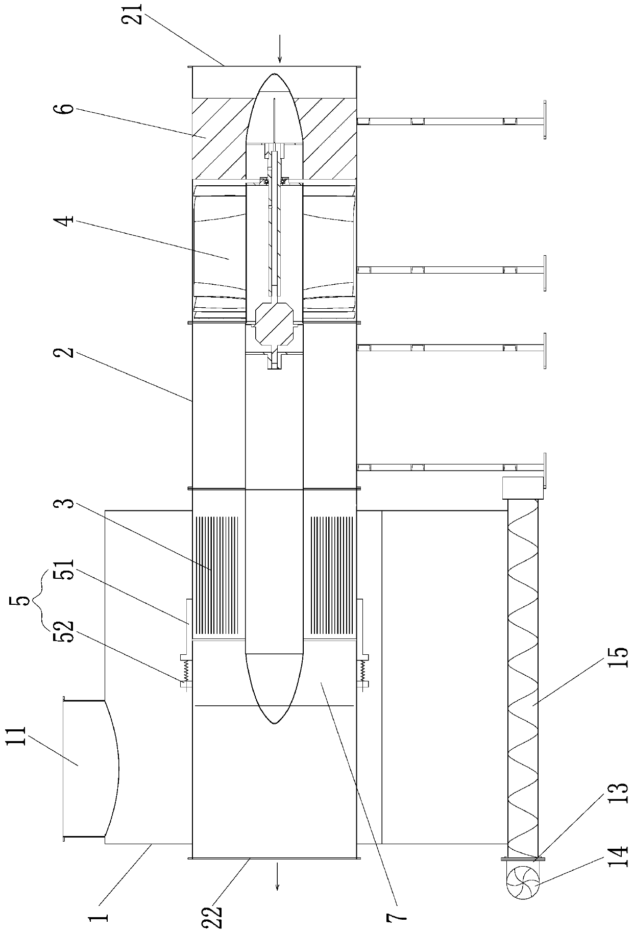
[0044] Such as figure 1 with figure 2 As shown, a supergravity dust removal device mainly includes a settling chamber 1, a main air duct 2 and a fan 4, one end of the main air duct 2 is an air inlet end 21, and the other end is an air outlet end 22. In this embodiment, The main ventilation channel 2 is divided into two parts along its axis: the forward air channel and the rear air outlet channel. The front and rear parts have an axial interval to form an annular dust outlet channel 3 covering the entire circumference of the main air channel 2. , and the caliber of the rear outlet air passage is slightly smaller than the caliber of the forward air passage, the fan 4 is arranged in the forward air passage, the axial direction of the fan 4 is along the axial direction of the main air passage 2, and the blower fan 4 is allowed to enter from the air inlet end 21 during work. The dust-laden gas not only performs centrifugal movement but also moves axially along the main air passag...
Embodiment 2
[0054] Such as image 3 As shown, the difference from Embodiment 1 is that the dust outlet flow channel 3 is a plurality of long slits set at intervals along the circumferential direction of the main air channel 2 on the wall surface of the main air channel 2, and the long slits The openings are evenly distributed in the circumferential direction of the main air passage 2, and the long slits are in a straight line along the axis of the main air passage 2. The long slits cover a certain length of the axis of the main air passage 2 and rotate along the main air passage 2. The dust ring moving forward can all enter the settling chamber 1 through the long slit to ensure the adequacy of dust removal;
[0055] Similarly, the dust outlet flow channel 3 is also provided with an adjustment assembly 5 for adjusting the opening of the dust outlet flow channel 3. The adjustment assembly 5 includes an annular adjustment ring 51 and a driving mechanism 52. The adjustment ring 51 is sleeved ...
Embodiment 3
[0060] like Figure 5 As shown, the difference from Embodiment 1 is that the supergravity dust removal device is a vertical structure, that is, the air inlet end 21 and the air outlet end 22 are arranged in the vertical direction, and the air inlet end 21 is located on the lower side of the settling chamber 1. The air outlet 22 is located on the upper side of the settling chamber 1, the secondary gas outlet 11 is coaxial with the air outlet 22 and is located above the air outlet 22, the axis of the main ventilation channel 2 is along the vertical direction, and the settling chamber 1 is supported by The structure is fixed, and the two sides of the lower part of the settling chamber 1 are respectively provided with cone buckets 12, and the bottom of the cone bucket 12 is provided with a dust discharge port 13. When the vertical structure is adopted, the dust outlet flow channel 3 is located in the middle area of the settling chamber 1, so that the high dust-containing gas ent...
PUM
| Property | Measurement | Unit |
|---|---|---|
| particle size | aaaaa | aaaaa |
Abstract
Description
Claims
Application Information
 - R&D
- Intellectual Property
- Life Sciences
- Materials
- Tech Scout
- Unparalleled Data Quality
- Higher Quality Content
- 60% Fewer Hallucinations
Browse by: Latest US Patents, China's latest patents, Technical Efficacy Thesaurus, Application Domain, Technology Topic, Popular Technical Reports.
© 2025 PatSnap. All rights reserved.Legal|Privacy policy|Modern Slavery Act Transparency Statement|Sitemap|About US| Contact US: help@patsnap.com