Small-diameter optical fiber and preparation method thereof
An optical fiber, narrow diameter technology, applied in the direction of clad optical fiber, glass manufacturing equipment, multi-layer core/clad optical fiber, etc., can solve the problem of reducing coating thickness, high cost of new coating materials, and difficult coating curing. and other problems to achieve the effect of ensuring macrobending requirements and meeting optical fiber transmission requirements
- Summary
- Abstract
- Description
- Claims
- Application Information
AI Technical Summary
Problems solved by technology
Method used
Image
Examples
Embodiment 1
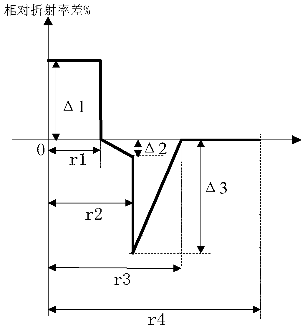
[0089] Using VAD+OVD process, with SiCl 4 、GeCl 4 、C 2 f 6 As raw materials, the core layer, optical cladding, and depression layer that meet the design requirements of the optical fiber preform section are prepared by changing the gas flow rate and ratio, as well as the moving speed and deposition times of the reaction zone during the production process; among them, the prepared powder rod , during the sintering process, dehydroxylation treatment is carried out by chlorine gas, and finally a transparent glass rod is formed.
[0090] Place the above-prepared glass rod in a specific vacuum high-temperature chamber for high-temperature homogenization treatment: within 2 hours, after rising from room temperature to 1250°C, keep the temperature constant for 20 hours, and keep the vacuum degree in the furnace at -0.3bar; then, fill it with N 2 Keep the pressure in the furnace at 0.5bar, keep the constant temperature for 6 hours, and operate at a temperature of 1250°C; in the sec...
Embodiment 2
[0095] Using VAD+OVD process, with SiCl 4 、GeCl 4 、SiF 4 As raw materials, the core layer, optical cladding, and depression layer that meet the design requirements of the optical fiber preform section are prepared by changing the gas flow rate and ratio, as well as the moving speed and deposition times of the reaction zone during the production process; among them, the prepared powder rod , during the sintering process, dehydroxylation treatment is carried out by chlorine gas, and finally a transparent glass rod is formed.
[0096] Place the above-prepared glass rod in a specific vacuum high-temperature chamber for high-temperature homogenization treatment: within 3 hours, after rising from room temperature to 1500°C, keep the temperature constant for 10 hours, and keep the vacuum degree in the furnace at -0.6bar; then, fill it with N 2 Keep the pressure in the furnace at 0.5bar, keep the constant temperature for 4 hours, and operate at a temperature of 1400°C; in the second...
Embodiment 3
[0101] Using MCVD process to SiCl 4 、GeCl 4 , SF 6 , Cl 2 As the raw material, the core layer, optical cladding, and depression layer that meet the design requirements of the optical fiber preform section are prepared by changing the gas flow rate and ratio, as well as the moving speed and deposition times of the reaction zone during the production process, and the transparent glass rod is formed by shrinking .
[0102] Place the above-prepared glass rod in a specific vacuum high-temperature chamber for high-temperature homogenization treatment: within 3 hours, after rising from room temperature to 1350°C, keep the temperature constant for 15 hours, and keep the vacuum degree in the furnace at -0.5bar; then, fill it with N 2 Keep the furnace pressure at 0.4bar, constant temperature for 6 hours, and operate at a temperature of 1350°C; in the second vacuum stage, keep the pressure at -0.5bar, 1250°C, and constant temperature for 15 hours; after the end, slowly cool down to 10...
PUM
| Property | Measurement | Unit |
|---|---|---|
| radius | aaaaa | aaaaa |
| thickness | aaaaa | aaaaa |
| thickness | aaaaa | aaaaa |
Abstract
Description
Claims
Application Information
 - R&D Engineer
- R&D Manager
- IP Professional
- Industry Leading Data Capabilities
- Powerful AI technology
- Patent DNA Extraction
Browse by: Latest US Patents, China's latest patents, Technical Efficacy Thesaurus, Application Domain, Technology Topic, Popular Technical Reports.
© 2024 PatSnap. All rights reserved.Legal|Privacy policy|Modern Slavery Act Transparency Statement|Sitemap|About US| Contact US: help@patsnap.com


